OEM Car Phone Modified to Make/Receive Calls

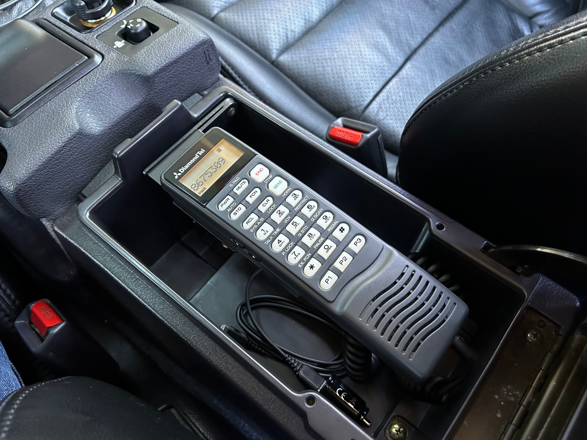
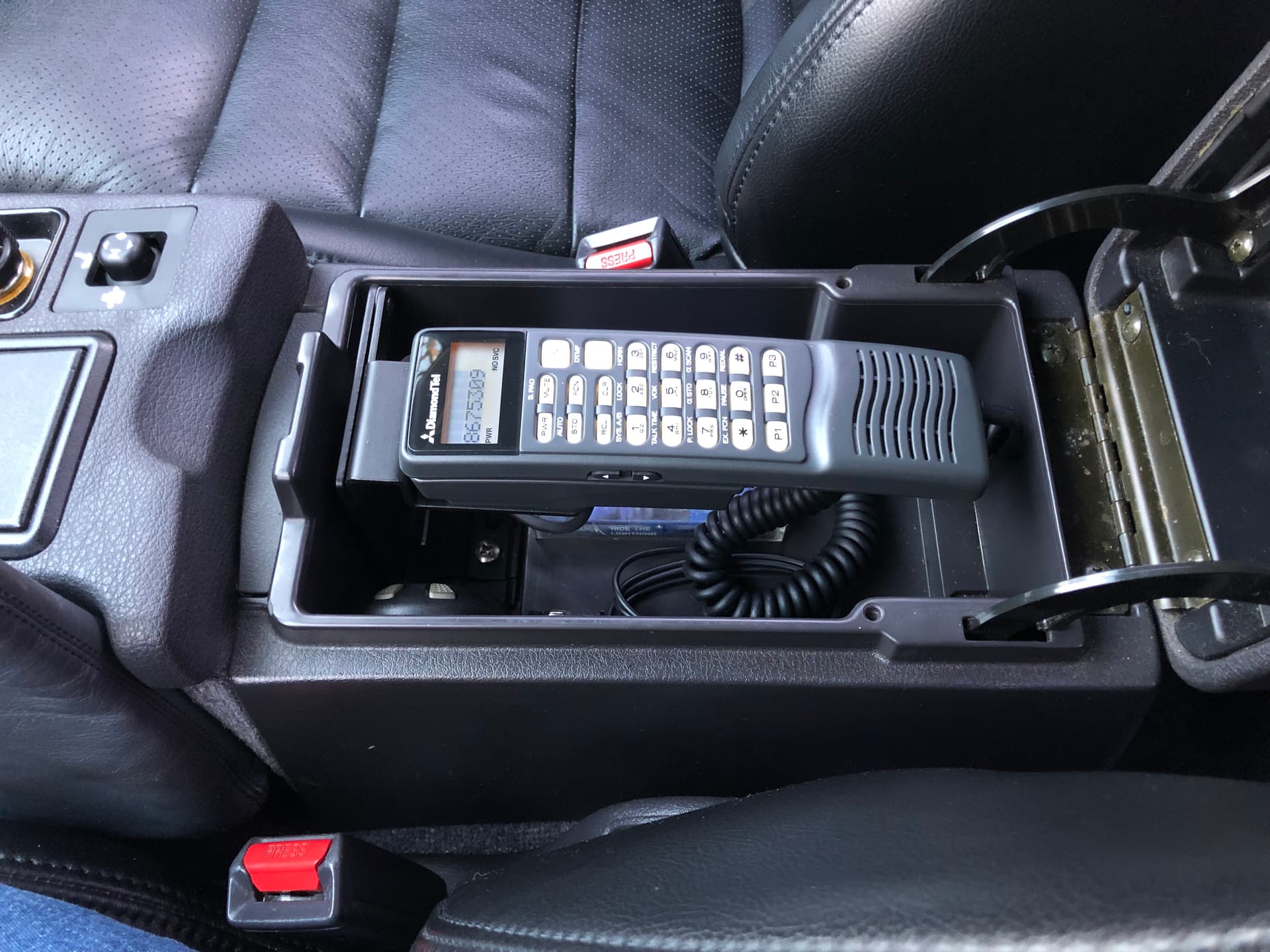
Over 2 years ago, I started gathering parts to replicate an OEM car phone installation in my 93 VR4 (3S Wiki article with info about the phone system). These phones used “1G” analog cellular service that has been extinct for about 14 years now, so it’s impossible to activate them to make/receive calls. I almost immediately started dreaming up ideas for how I could modify the phone to actually make/receive calls.

The obvious solution that many people have suggested is to hack up the phone handset with the internals of a Bluetooth headset. Nah. Not refined enough for me. It would lose all the charm of the original phone display, button sounds, etc., and would basically turn the car phone handset into a glorified speaker and microphone. I want the phone’s original display and buttons to function. I want the phone’s original ringer sound when there’s an incoming call. I want to be able to actually dial a number on the keypad, see the digits appear on the screen, then press “SEND” to make the call happen.

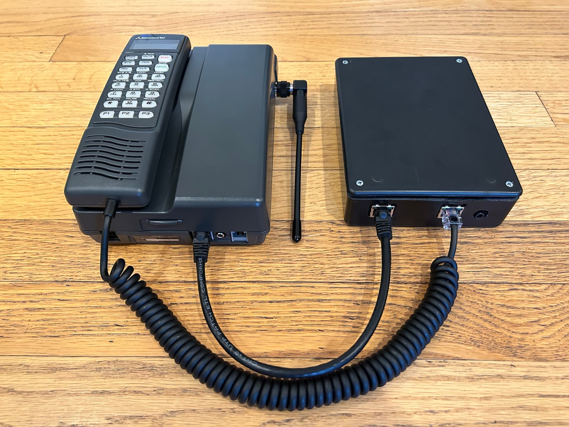
So I took a slightly more complicated approach that will give me everything I want without requiring any modification at all to the original phone. It all started with a dual RJ-45 socket “breakout” board that I can use to connect inline between the handset and transceiver. First I wired it up as a direct passthrough:

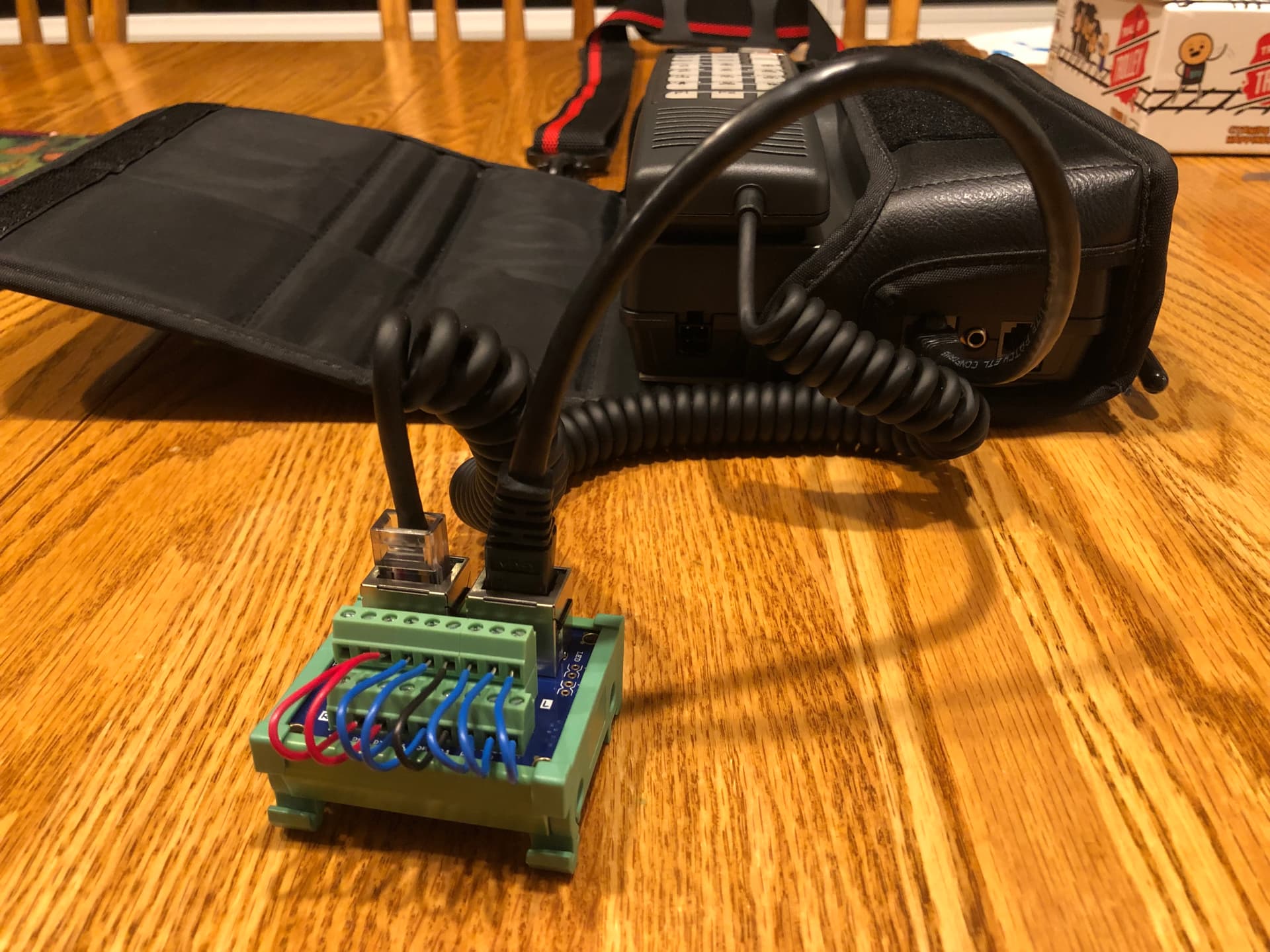
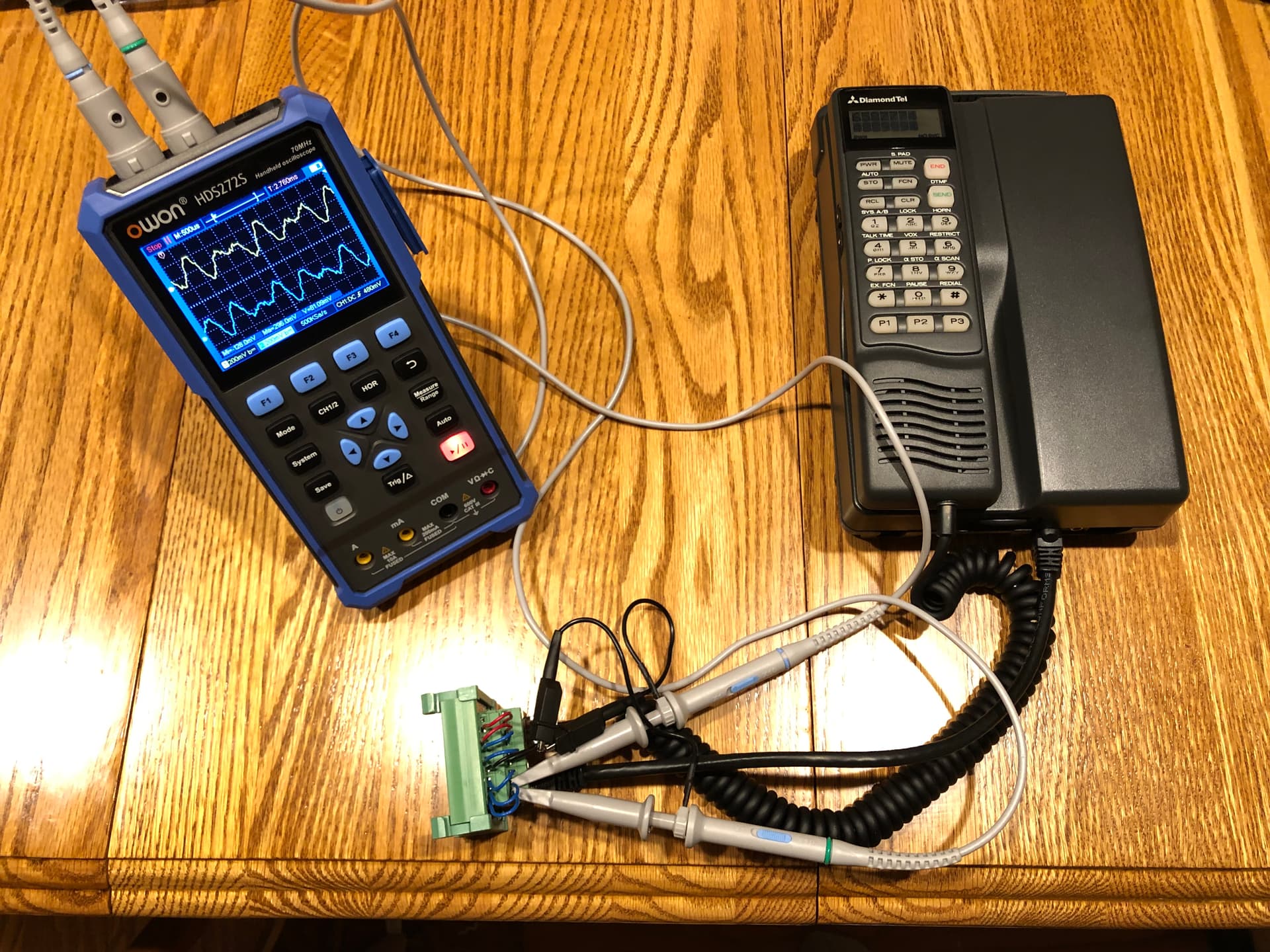
After some quality time with an oscilloscope, I had reverse-engineered what all 8 wires between the handset and transceiver are used for. I identified and decoded digital communications so that I could completely take over control of the handset:

  • Print any text I want to the screen, clear the screen, make the text blink, etc.
  • Control the “viewing angle” adjustment of the LCD display.
  • Turn all status indicators on/off at will.
  • Turn the backlight on/off.
  • Turn the 2 speakers and microphone on/off individually.
  • Detect the pressing and releasing of all button.
  • Detect when the handset is “on hook” or “off hook”.


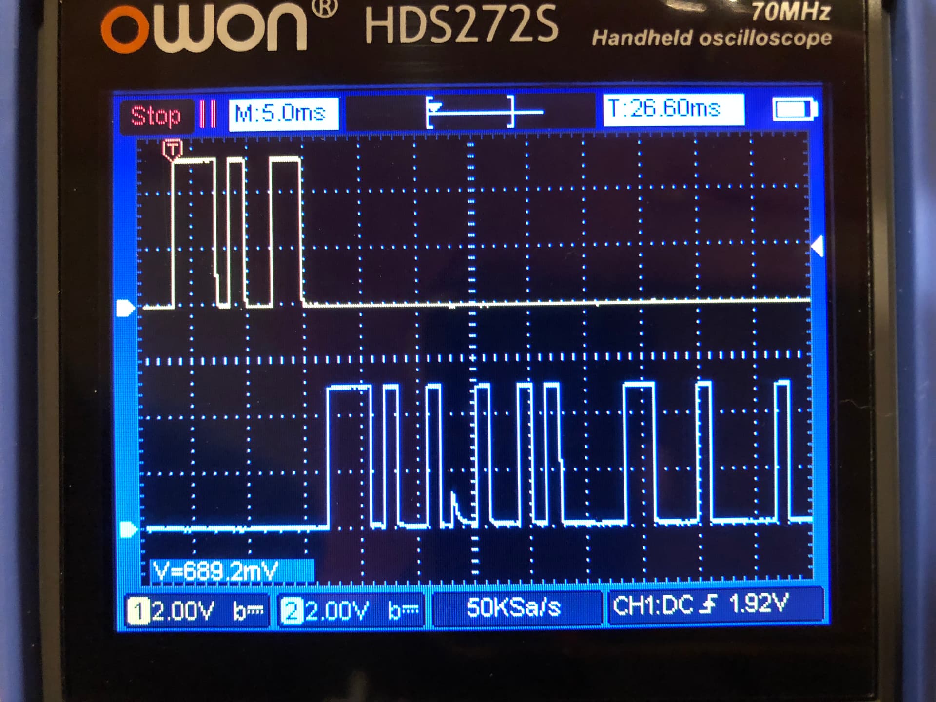
(Intercepted digital communications between the handset and transceiver)


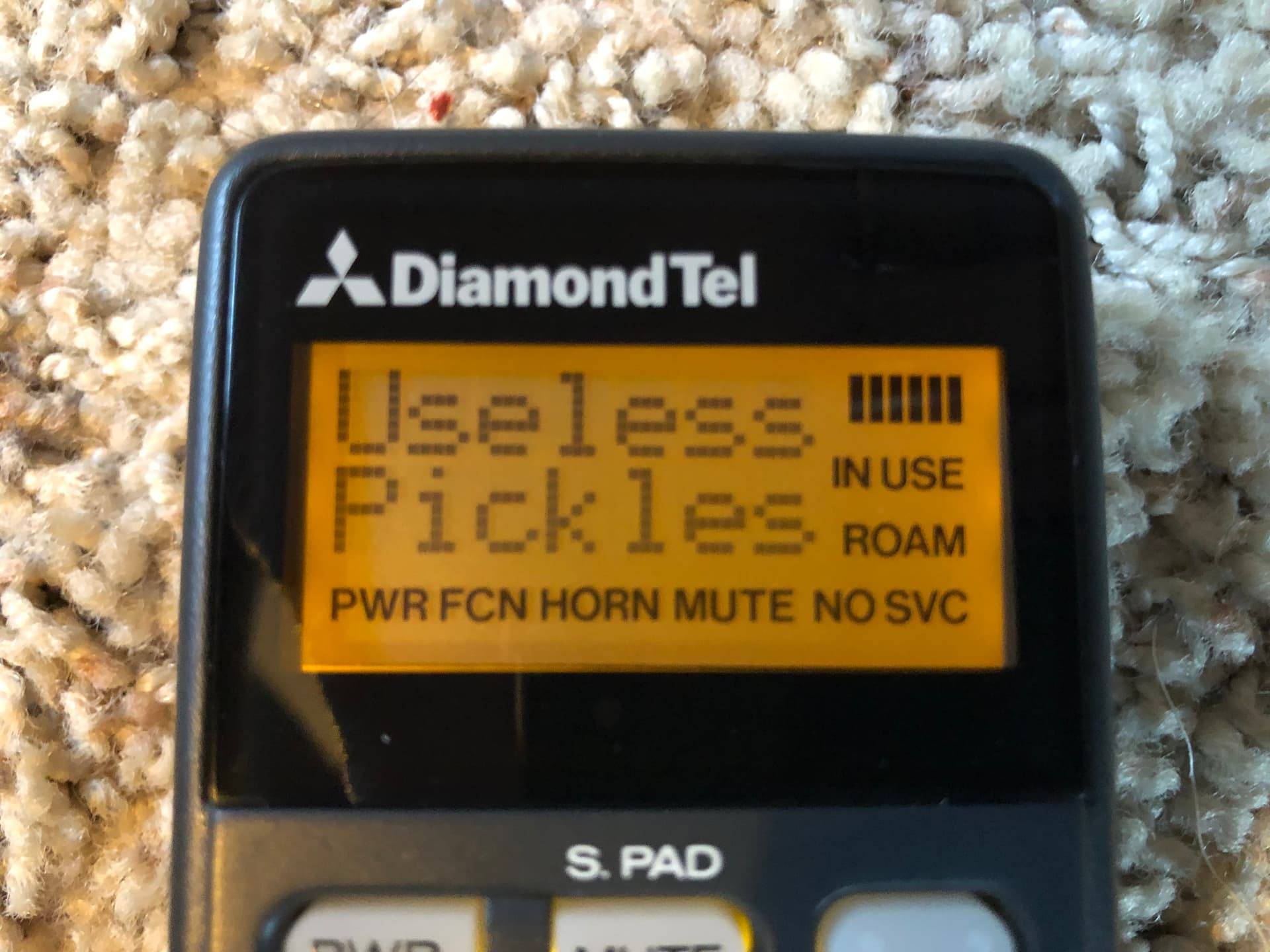
(early proof that I could control the handset)

Being a software engineer with some hobby experience in microcontroller (embedded) programming, this means that I could hypothetically make the phone do anything I want. The only limits are my imagination, and my electronics knowledge/skills (which are pretty weak).

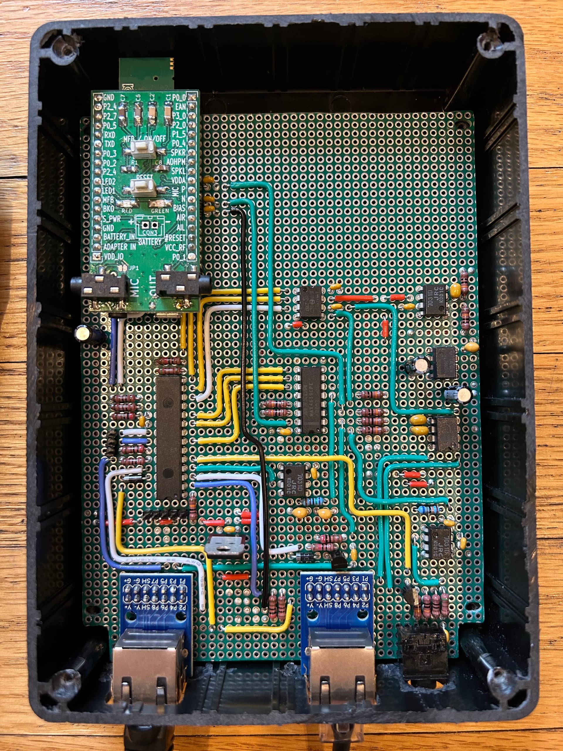
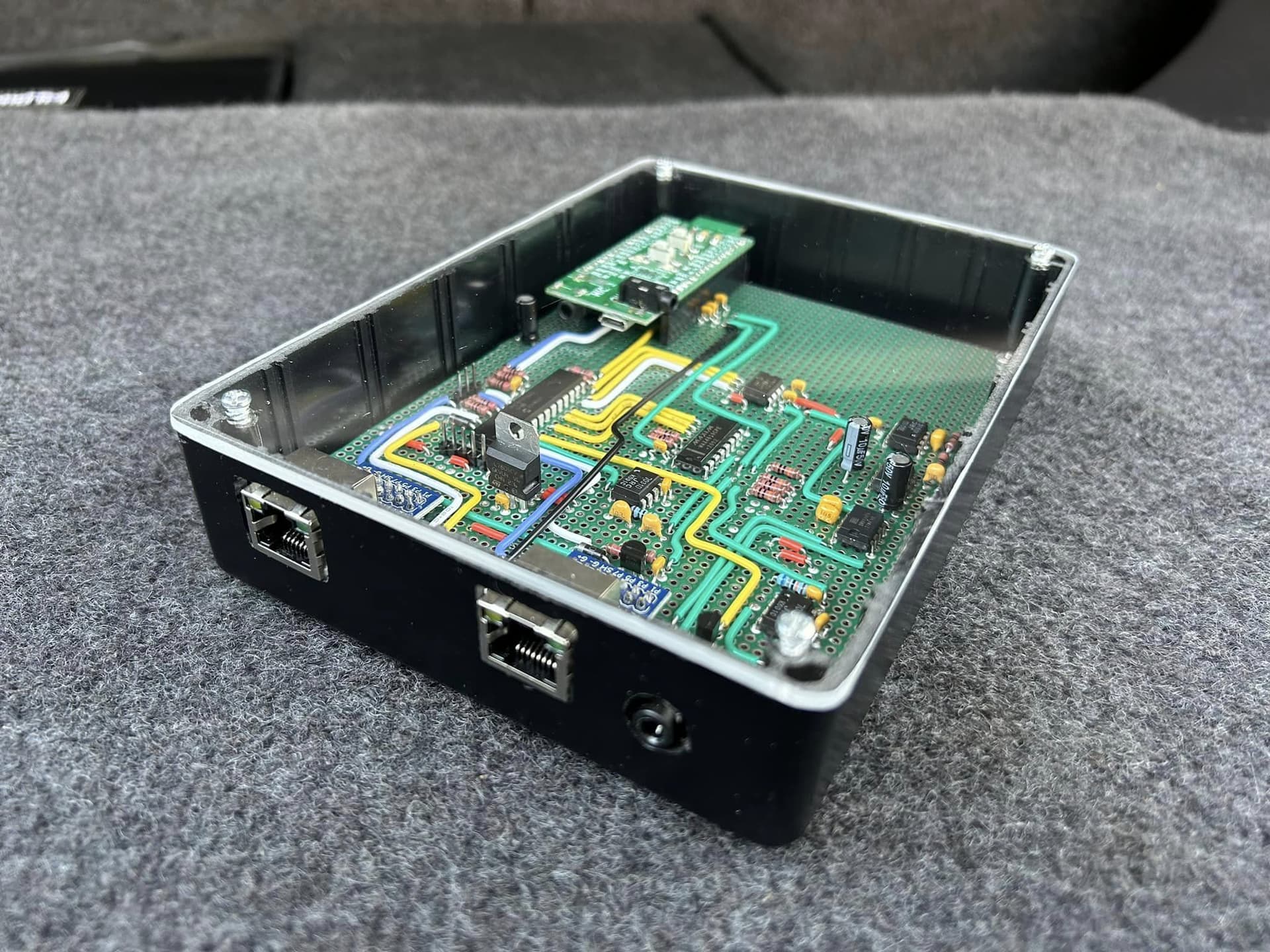
Here’s where I’m at now after a little more than 3 months of effort:

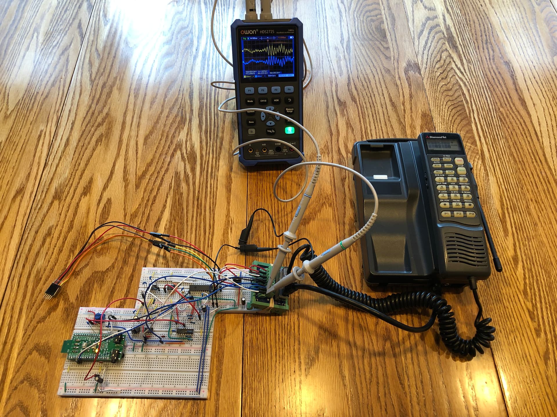
That mess on a breadboard is my custom Bluetooth adapter and complete re-implementation of a substantial amount of the original car phone functionality (still a work in progress, both the hardware and software).

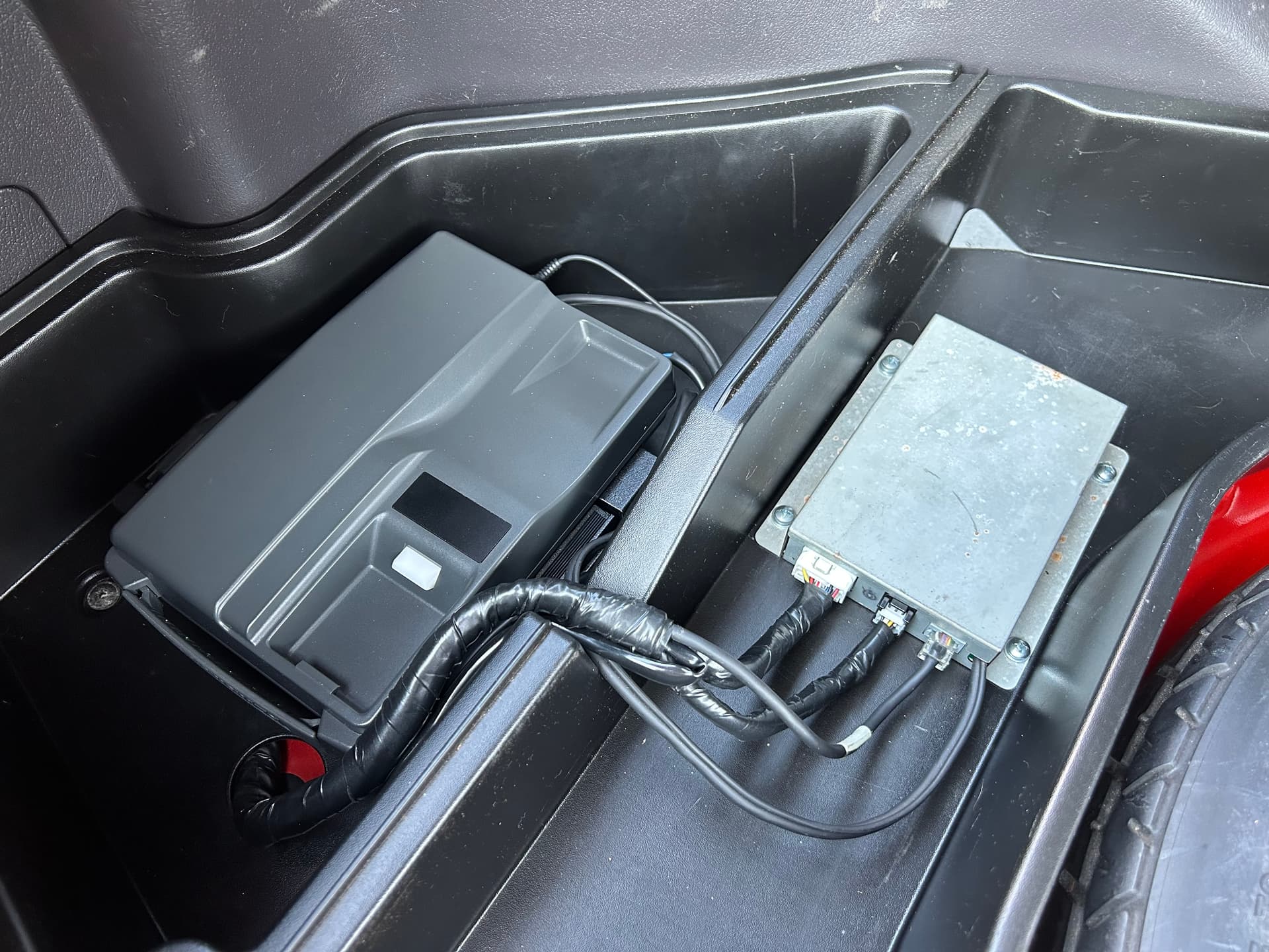
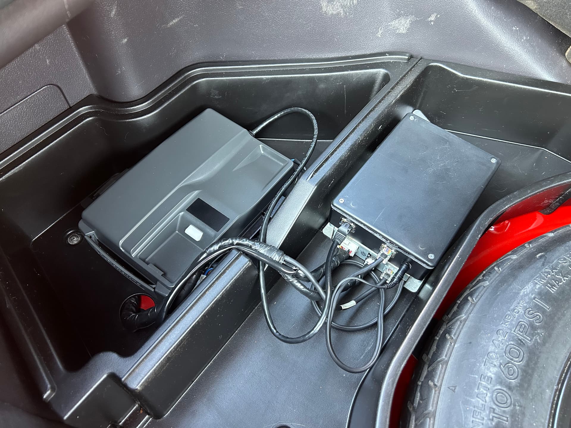
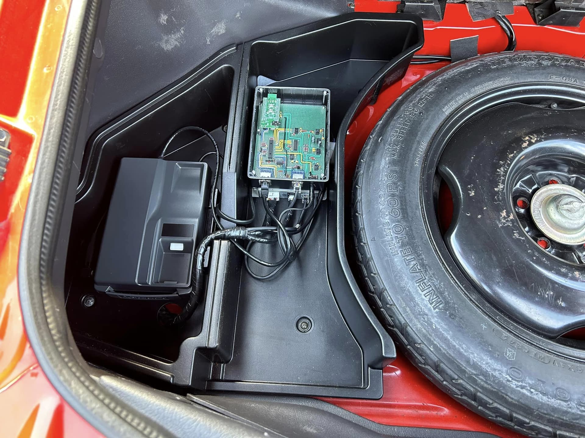
  • The original transceiver is being used only as a power supply and its power on/off functionality.
  • When the transceiver powers on, power is supplied to my circuit. The power supply and ground are passed through to the handset so that it also powers on.
  • There is no longer any digital communication or audio connection from the transceiver to the handset. Instead, my circuit connects directly to the handset audio and digital communication wires.
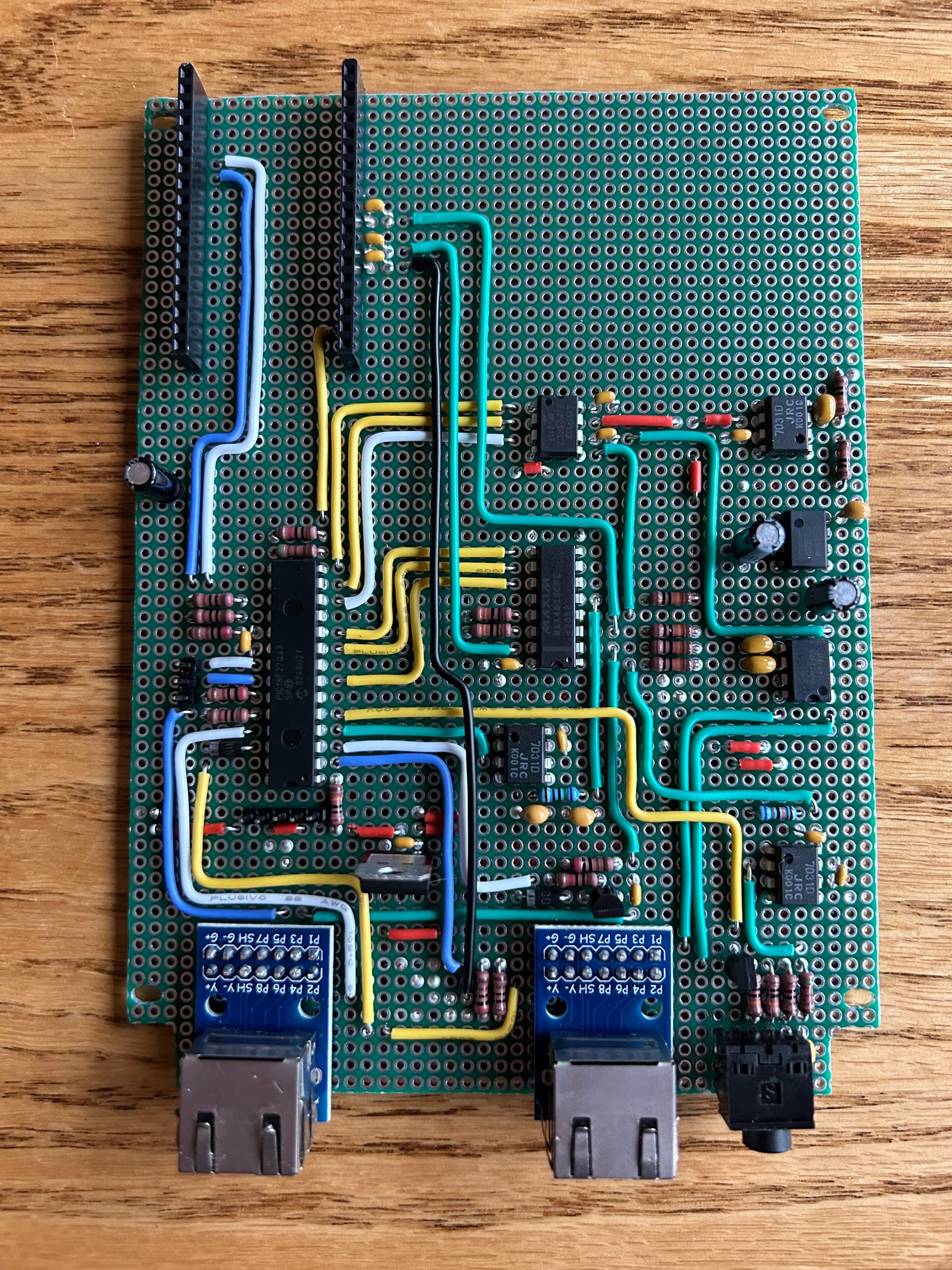
  • A microcontroller is custom programmed to implement all phone functionality and interface with both the handset and a Bluetooth module.
  • It can be paired with any modern cell phone that supports Bluetooth “Hands-Free Profile” (HFP). Once paired/connected, then the car phone can send/receive calls through the modern cell phone.

Here’s a video showing off some of the functionality (including both incoming and outgoing calls):

I’ve posted several other videos demonstrating various other features. Check my youtube channel for more.

The handset is basically a dumb display, microphone, and pair of speakers, so I had to rebuild all the functionality from scratch. A surprising (to me) amount of effort has gone into audio:

  • I have to generate my own sounds for button presses, ringtones, etc.
  • I have to manage volume levels of sounds myself. There is no volume control built into the handset.
  • There is only one channel of audio input to the handset, so…
    • I have to manage turning the appropriate speaker (ear speaker or loud speaker) on/off depending on where I want the sound to come out.
    • I have to manage switching between audio sources (voice audio from Bluetooth, or generated tones/beeps from my microcontroller).
    • This gets quite complicated when different types of sounds can come from different sources, have independent user-adjustable volume settings, need to be sent to different speakers on the handset, and one of these sounds can “interrupt” the other. For example, incoming voice audio from the Bluetooth module when in a call plays out of the ear speaker (when “off hook”), but then pressing a button needs to play a button beep sound from the microcontroller at a different volume level through the loud speaker.
  • Most of the complexity in my circuit is all about audio:
    • Op-amp to boost the power of the raw output from the microcontroller.
    • Low-pass filter to smooth out the digitally-generated sound.
    • Switching circuitry/IC for controlling multiple audio flows (enable/disable mic output from handset to Bluetooth; switch between Bluetooth and microcontroller generated sounds as input to the handset).
    • Digital potentiometer to control volume.
    • Special op-amp for generating an inverted “copy” of the audio for the handset.
      • Handset uses “differential” audio input to help minimize noise interference on the audio signal (noise on both wires cancels itself out when the handset subtracts one signal from the other to produce a single audio signal).
      • Requires an additional component on the board to generate a negative 5V power supply.

I have quite a bit of the original phone’s functionality replicated:

  • 5 separate volume levels can be adjusted.
  • Adjustable LCD viewing angle.
  • Recall the last called number.
  • 3 speed dial numbers (P1, P2, P3 buttons).
  • Directory of saved names and phone numbers.
  • Passcode-protected storage of credit card numbers (which can be referenced in saved phone numbers to be sent as dial tones after establishing the call).
  • Keeps track of time spent in the current call. You can view the time spent in the last call, and total accumulated time spent in calls.
  • Ability to mute the microphone when in a call.
  • Ability to mute all button press sounds when in a call. You can dial an entire string of digits onto the display, then press a button sequence to send it all as dial tones (like a conference call room code).
  • An optional “warning beep” 10 seconds before the end of every minute while in a call (per-minute prices were high back in the day!)

I also added several ringtones to choose from.

I’ve hit the wall of getting 80% done with 20% time invested. I’m dealing with all the difficult remaining 20% of the project:

  • Audio issues caused by hardware/circuitry.
    • “pops” in the audio when turning on the speaker, switching between audio sources, etc.
      • Sometimes induces interference onto the digital communication lines and makes random stuff happen on the handset.
    • Digital noise in the audio.
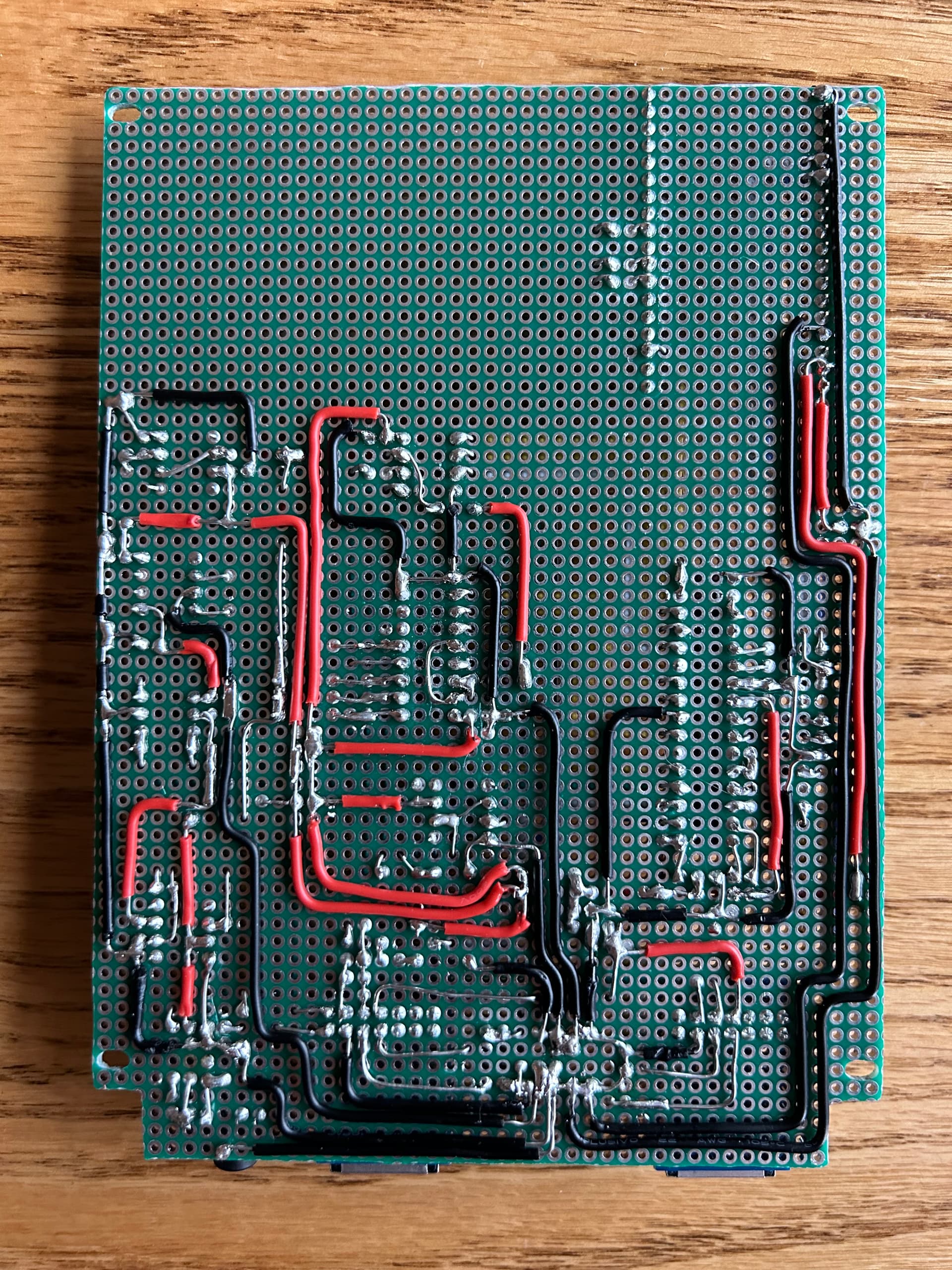
      • Some is likely just from being a sloppy circuit on breadboards.
  • Lots of sloppy code that results in intermittent strange bugs, like getting stuck when trying to make a call (requires a power cycle to recover from it).

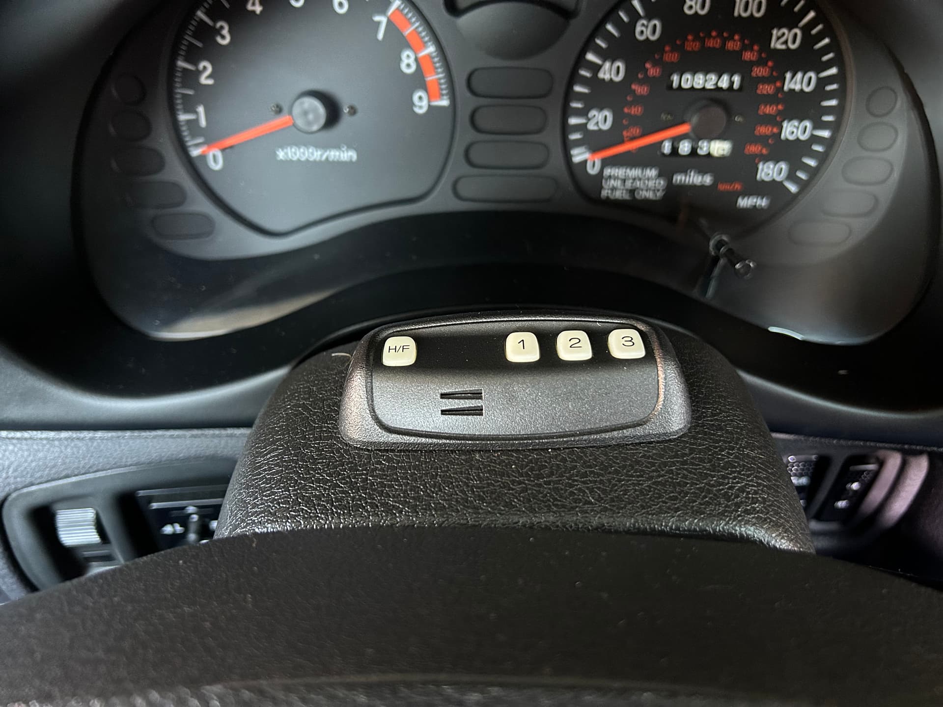
I also need to obtain a working “hands-free controller unit” or repair the one I have (water damage), then add additional circuitry to interface with its microphone output so I can take full advantage of the OEM hands-free integration with mic/buttons on the steering column and phone audio hijacking the car speakers.

If you made it this far, then thanks for reading! As a reward, here’s a demonstration of some ringtones I programmed for the phone:

If you are interested in more technical details, then check out this thread on an electronics forum where I detailed my progress from the beginning (including all the reverse-engineering), and got a lot of help frome people that know electronics way better than me: Making a Bluetooth adapter for a Car Phone from the 90's | Electronics Forum (Circuits, Projects and Microcontrollers)

13 Likes

I take my hat off to you. That is real dedication and a fantastic demonstration of what can be done by a true professional.

3 Likes

Impressive!
Re. pops heard: Have you considered implementing a zero-crossing-detector with initiating the audio signal? i.e. only turning on the speaker or switching sources when the a/c signal crosses the zero point?
Or possibly increasing the amplitude of the signal over a few milliseconds of time before going full volume with it.
Good luck!

1 Like

Amazing work. Just hope that some day we can possibly get “kits” from you to do the same with our cars. :slight_smile:

2 Likes

Thanks :slight_smile:. I am actually a professional software engineer, so the programming portion of this project is well within my comfort zone. The electronics/hardware portion of this project is all amateur :laughing:.

I think I’m still battling some DC voltage mismatch on either side of the switch in some situations, even though I have attempted to bias to 2.5V on all inputs/outputs of the switch. I think the potentiometer and/or the handset “drawing” power from the audio signal is messing with the voltages in some way? The voltage between my switch and the volume control pot drops substantially when sound is actually coming out the handset.

I still have a few ideas to try. I think I might need to add another op-amp in there somewhere to prevent to prevent voltage from dropping in a certain area of my circuit? My trouble is that I can barely communicate intelligently about this stuff to explain what I know, where I’m at, and what my problems are. But I’ve been slowly stumbling through it with some trial & error, googling, and some guidance from people on the electronics forum.

I have doubts that I’ll be able to ever get this beyond the point of prototype quality that would feel comfortable replicating and selling, but I do plan on publishing all the technical info, circuit diagrams, source code, config files, and pre-compiled binaries so that anyone some soldering skills and some tech-savvy could replicate what I’ve done.

2 Likes

Follow-up to this. I just figured out that I had the digital pot connected up wrong. I won’t try to explain because words are hard and I don’t feel like drawing diagrams to properly explain, but I seem to have solved all the severe “pops” in the audio that were associated with switching between different audio source and/or between different volume settings.

I have found that there are some digital pots out there that are specifically designed for audio (log audio taper instead of linear, and built-in zero-crossing detection), but I don’t think it’s necessary. The “pops” caused by this are minuscule compared to what I was dealing with.

As for trying to apply zero-crossing detection for the timing of turning speakers on/off, I think this would be practically impossible. Turning the speakers on/off involves sending a a UART command at a snail’s pace of 800 baud to the handset, then there’s some processing time on the handset before the change applies (which may depend on whether there are other UART commands queued up, etc.). Turning the master handset audio circuit on seems to take even longer (around 250 ms). I’m already accounting for some of these delays. Basic approach (when I need to turn a speaker on, or swiitch which speaker is in use) is:

  1. Disable my volume pot (cut off sound input to the handset).
  2. Send commands to turn speakers on/off as necessary.
  3. Wait for UART TX command queue to empty (all commands sent to handset).
  4. Switch audio input source if necessary.
  5. Change volume pot wiper position if necessary (different volume setting for new sound source)
  6. Wait a hardcoded amount of time based on experimentation (20 ms if just switching speakers, 250 ms if turning the master audio on).
  7. Enable the volume pot.

I think the light “popping” from temporarily silencing the audio during the switch helps mask any AC popping from not having zero-crossing detection. But I will keep in mind that I could possibly improve it a bit more by switching to a more appropriate digital potentiometer. But zero-crossing detection on the potentiometer won’t help with switching between completely different sound sources.

I don’t need to make this the most perfect audio quality. I just want it to be not obviously “bad” sounding, and not inducing interference in the digital communications due to huge voltage spikes.

(BTW - Thanks for introducing me to the concept of zero-crossing detection. I learned something new today :grinning:)

Awesome work! I used the ZCD back when I was switching 240v 50A circuits, so it’s probably an overkill in this situation. I personally prefer the brute force method like you’re using (hardcoded time delta) since it’s simpler (KISS principle)… and you’re being careful to ensure it’s not going to blow your subwoofer cones through the rear window.

I have some new features implemented:

  • View/edit the Bluetooth name of the car phone.
  • View the Bluetooth name of the paired modern cell phone.
  • Caller ID for incoming calls!
5 Likes

Here’s a demo of the car phone actually being a car phone… in my car!

I’m still far from done:

  • I need to integrate with the hands-free controls, stock radio, and front right speakers of the car.
    • I have a damaged original hands-free controller unit that would take care of much of this for me automatically if I can get it working.
    • I might need to give up on the original controller unit and build my own circuitry.
  • It’s still a sloppy breadboard prototype, temporarily stuck to the trunk carpet with velcro. I can’t really finalize the circuit and move to a soldered prototype board until I figure out the hands-free integration.
5 Likes

Damn! NICE job! Looks good enough for gummint work, and better get crackin’ on picking up the milk for wifey…

1 Like

Wow! I like your attitude towards the naysayers! I am sure you were told ‘It can’t be done!’ many times before you posted this.

3 Likes

I dealt with many naysayers when I was just trying to find info about the phone option at the very beginning (before I even considered trying to make one actually work). Many people told me there was no such thing as an OEM phone option, and that there is no factory wiring for a phone in the car. This was despite me sharing photos of parts of the sales brochure that specifically said the car is pre-wired for an official cellular telephone accessory.

Then I’ve hand plenty of people respond to my search for all the OEM car phone parts (and my efforts to make it work) with many variations of: “Why would you want this? You won’t be able to make calls with it”, or, “Why not just install a modern aftermarket head unit with Bluetooth support? Then you can do hands-free calling in the car with your cell phone”.

I guess these people legitimately thought that my main goal was to be able to have phone conversations in my car (by any means), and that I was going about it the wrong way.

4 Likes

Hey! let me be the first to tell you, they don’t make them like they used to! This phone would probably work under water. Definitely getting some Miami Vice vibes here. Nice job.

3 Likes

In an effort to further modernize this old car phone, I have added some games to it :laughing:

This phone was released 5 years before Nokia introduced the world to mobile games with their Nokia 6110, so I’ve really made this phone “ahead of its time” now. The Nokia had 3 games: Snake, Memory (flip cards over to find matching pairs), and Logic (similar to Mastermind).

This all started as a conversation with my kids about what games I could make for the phone, and one of them suggested Snake. We laughed about how ridiculous that game would be on a 7x2 grid. But it would technically work and it would be funny. So I did it:

I proudly showed it to my wife, and she got frustrated with the game and quickly declared that she hates it. In need of approval from my wife, I went back to the computer and started working on a second game that was more her style: Memory

It was successful in getting the wife’s approval, but it left me dissatisfied. This game was actually more complicated to program than Snake, but the end result wasn’t very exciting. I needed something that really felt like a legitimate game that was somewhat interesting and challenging, and less of a gimmick than a snake that can only do a few laps between 2 rows before the game ends.

I considered a remake of the 3rd Nokia game (Logic), but there’s not enough room on the screen to display all the necessary information in a usable way. I thought of a way to technically do it, but it would be very cryptic and not very fun.

So I went back to the kids for suggestions, and this time I was challenged to make Tetris! Again, we first laughed about how ridiculous Tetris would be on such a small playfield, but then started thinking through it and came up with a way to make it work:

  • Pieces would need to “fall” sideways instead of down.
  • Pieces would be limited to no more than 2x2 in size, so they would have to be non-traditional Tetris shapes.
  • 2 of the shapes can fill the entire width of the playfield, so I can’t allow single lines to be cleared out. A minimum of 2 consecutive lines must be filled to be cleared out.

And you can’t have Tetris without the iconic background music, so I went all out with more complex sound effects than the previous games, and background music. The music is an adaptation of a sheet music arrangement I found for an accordion solo :laughing:

Tetris turned out much better than I expected. It really feels like a game. I implemented the automatic increasing level of difficulty and scoring similar to the NES version of the game, with the option to start at any level. Not shown in the video: I added high score tracking today, so now there’s replay value (try to beat that high score).

That might be the best I can come up with. Any suggestions for another game that might adapt well to this old car phone?

8 Likes

I’m going the extra mile to replicate a substantial amount of original behavior of the phone as authentically as reasonable (or maybe beyond reasonable). I previously didn’t really know exactly how the phone worked when it had service, when it was making/receiving a call, or when it was in a call. I could only guess based on vague descriptions of features in the owner’s manual.

But now I can experience the true original behavior thanks to obsolete mobile service testing equipment! This equipment simulates a cellular base station and allows you to simulate incoming/outgoing calls (among a lot of other important stuff for testing/developing phones back in the 90’s that I don’t care about). Here’s a demo of the service tester performing all the main functions:

I’ve already discovered many details I had wrong or just didn’t know about at all previously. For example, the “cadence” of my ringtone was wrong (length of each “ring”, and amount of silence between each “ring”). I’ve now updated it to match the original ringtone exactly. And while putting together a video to compare some original behavior to my Bluetooth adapter behavior back-to-back, I even discovered that the sound of the ringtone itself was wrong!

Here’s a video comparing some some of the basic behavior of my Bluetooth adapter to the original behavior (the “smoother” ringtone option at the end is the incorrect sound I’ve been using for about a year).

The power-on sequence has to be a bit different just because the Bluetooth adapter needs to be able to distinguish between “no Bluetooth connection” (flashing NO SVC) and “Bluetooth connection, but no cell service” (solid NO SVC). I also use a distinct sound effect for Bluetooth connect and disconnect.

Here’s another video showing various connection/service status changes with the Bluetooth adapter. After the Bluetooth connection is established, changes in cell service status are practically identical to the original behavior (appropriate indicator on the display, along with a notification beep).

5 Likes

My car phone Bluetooth adapter now supports the original “hands-free” system for the Mitsubishi 3000GT! Well… at least good enough for a demo. Here’s a tour and demo of the system.

It’s a long-ish video, so I setup “chapter links” in the video description in case you want to skip the explanation stuff and jump straight to some demonstrations.

There’s still some major issues with excess noise in the hands-free microphone signal, and audio from the speaker echoing back to the person on the other end of the call through the microphone. I need to rebuild the entire circuit with soldered connections to get rid of the noise before I can really work on tuning volume levels and echo cancellation.

3 Likes

I finally built a more sturdy prototype, resolved most of my audio quality issues, and got the entire system installed in my car. I now have a complete and fully functional factory car phone system in my car, able to make/receive calls, use the original hands-free system, and even use modern voice dialing/commands.

Here’s a video tour/demonstration of the completed system:

Here’s some pictures of the new Bluetooth adapter prototype:

And some pictures of the installed components:

7 Likes

That’s quite a project you’ve completed. Well done.

2 Likes

Hackaday wrote a blog post about my project!

7 Likes

I’ve received a few comments about my prototype circuit board looking “like art”, so I decided to display it as art! I made a clear polycarbonate lid for the project enclosure so that the circuit board will be visible any time I show off the car phone system in the trunk.

3 Likes