OEM Car Phone Modified to Make/Receive Calls

Here’s a demonstration of what my voice sounds like on the other end of a call from my vintage car phone. This is with the improved hands-free microphone audio quality after I replaced a bunch of capacitors in the hands-free controller unit. Yes, it was even worse before. This might just be the audio quality of a hands-free car phone system from the early 90’s.

4 Likes

Reviving this thread because I’m working on a major improvement to my car phone Bluetooth adapter. I’m redesigning it so that it no longer requires the original car phone transceiver to provide power management. My circuit will now be completely self-sufficient with its own li-ion battery supply, a direct connection to the vehicle power supply and ignition connector, and manage its own power on/off behavior.

And best of all, I’m designing it to fit INSIDE of the original car phone transceiver, replacing the original circuit board, but using the same types of connectors positioned exactly in the right place. The end result will be a completely original-looking car phone with no externally visible signs of modification, no external “plug-n-play” modules.

Here’s a 3D render of the main circuit board:

I printed it out on card stock paper to confirm that everything will line up properly in the original transceiver case:

A separate small circuit board will contain the Bluetooth chip and a few supporting components. This needs to be mounted outside of the metal transceiver case, but still inside of a plastic cover on the transceiver. The metal case would block the Bluetooth signals.

And I recently mocked up a portion of the new circuit design on a breadboard so that I could test all the new power management stuff, including writing new microcontroller code to deal with detecting approximate battery level, when the power button is pressed, when external power is connected, when the ignition is turned on/off, etc., and decide if/when to power on/off.

In that last photo, you can see the first version of my Bluetooth “daughterboard” (bottom center of photo), an off-the-shelf Li-Ion battery module that I customized a bit (right), and the external power supply connection with a switch to simulate ignition on/off (bottom right).

I’m now quite confident that I can pull this off. I just have a few more details to test/refine about the main circuit board before I send the designs out to be printed. I hope to have my first attempt completed in about 4-6 weeks.

If you want all the technical details, you can follow my progress here: Making a Bluetooth adapter for a Car Phone from the 90's | Page 9 | Electronics Forum (Circuits, Projects and Microcontrollers)

2 Likes

Amazing work buddy. Looking to see the future on this one.

1 Like

I think the rest of us are waiting to get our own boards for purchase so we can do the same thing to our cars. :sunglasses: :+1:

1 Like

If I’m successful and can refine the design to the point that it is practical to do so, I will consider selling conversion kits. I’m having trouble finding some components of specific shapes/sizes that will allow for a simple “drop-in” replacement of the the phone’s original circuit boards and connectors, so it will likely require some minor grinding of a few internal parts to make clearance. You’ll also have to source your own DiamondTel Model 92 telephone.

I’ll also be publishing the circuit and PCB designs, microcontroller source code, etc., free for personal use, so anyone could hypothetically replicate my adapter for just the cost of parts and PCB fabrication, plus time and effort to assemble everything and install software/configuration on the microcontroller and Bluetooth chip.

1 Like

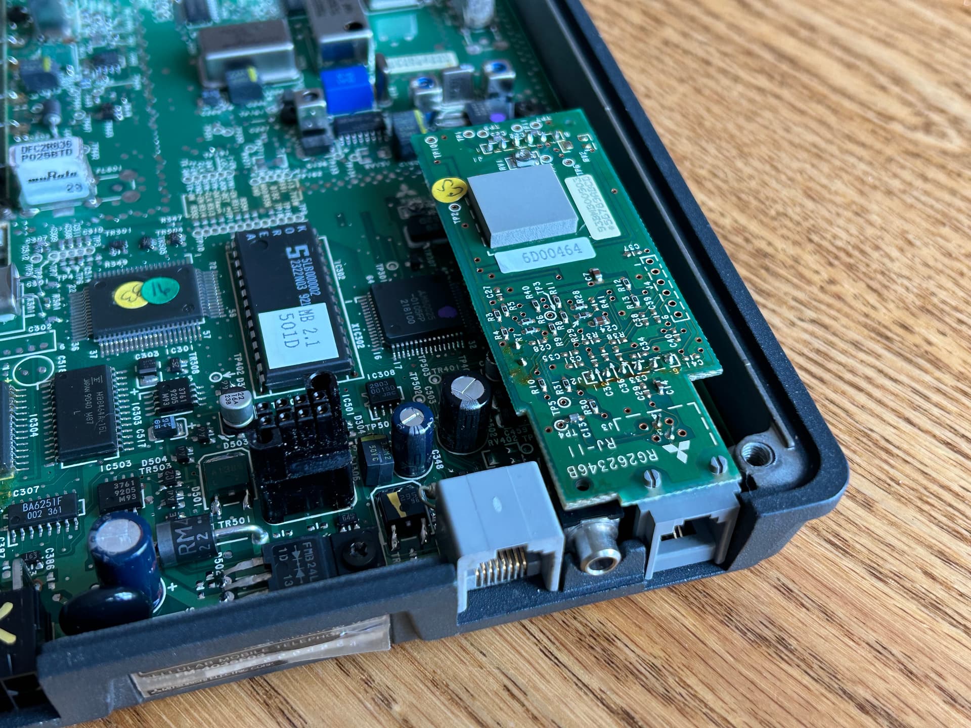
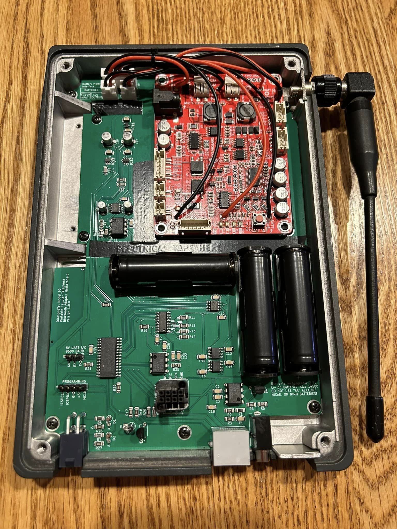
I’ve made some good progress. I’ve solved the problem of how I will mount the Bluetooth module in the plastic “cover” for the transceiver and connect it to the “motherboard” inside of the metal transceiver case.

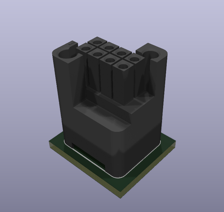
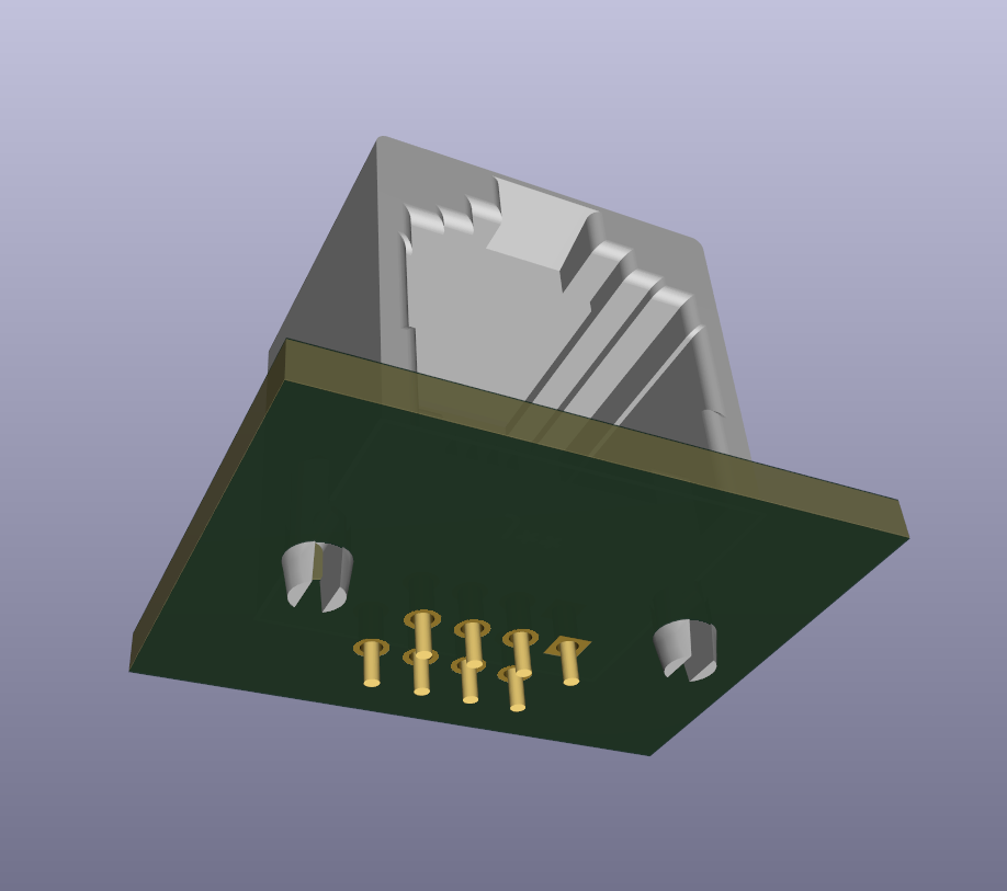
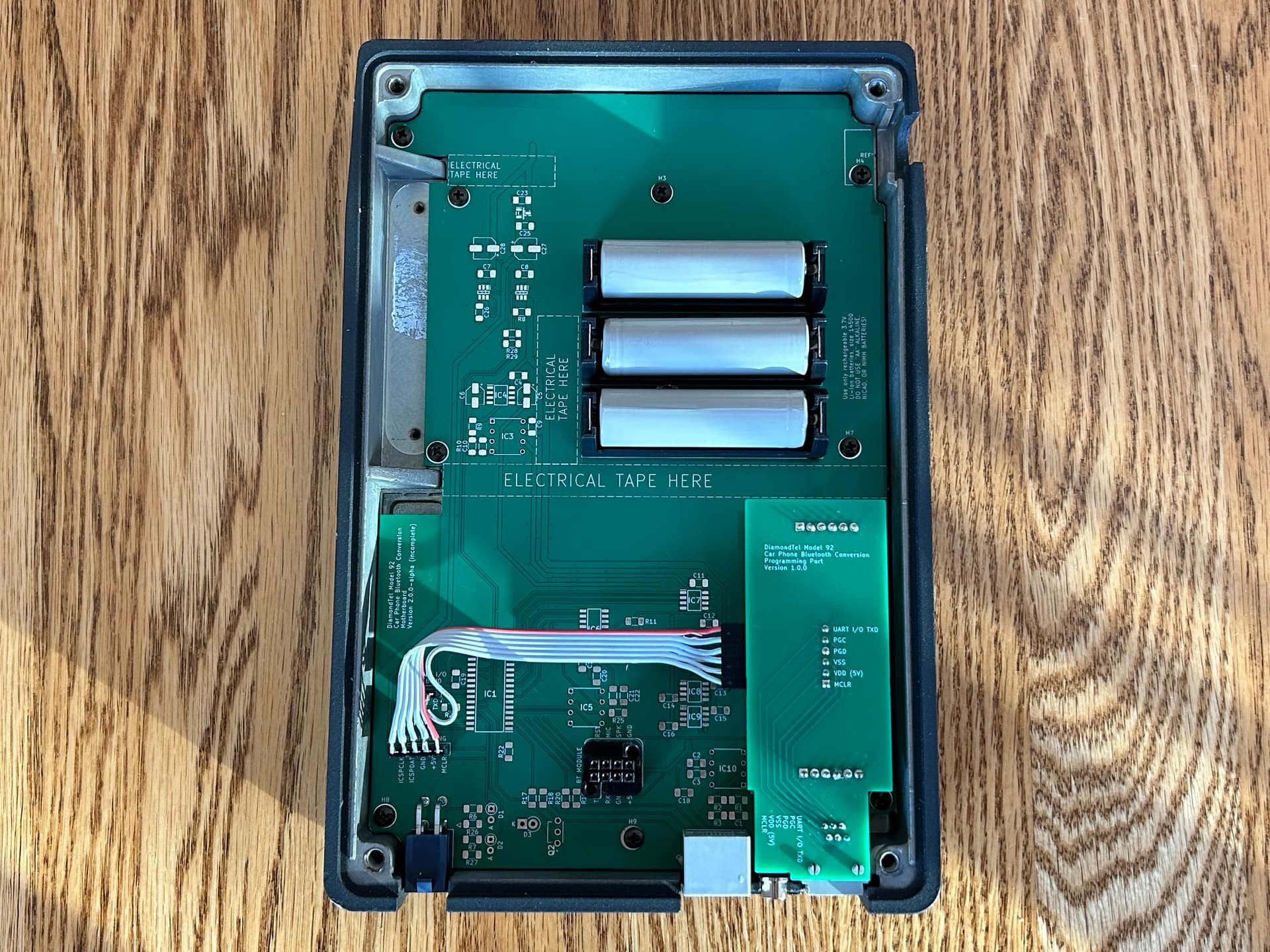
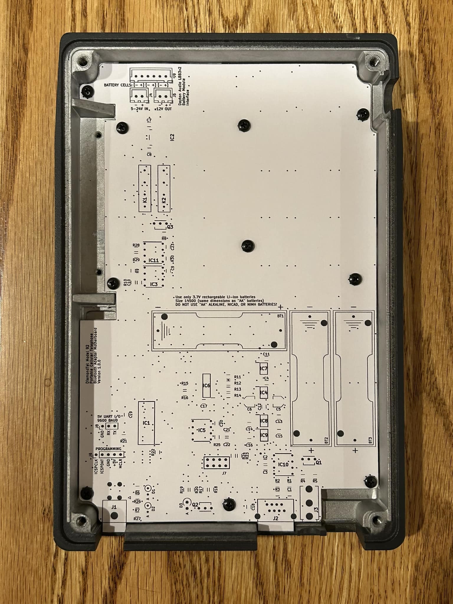
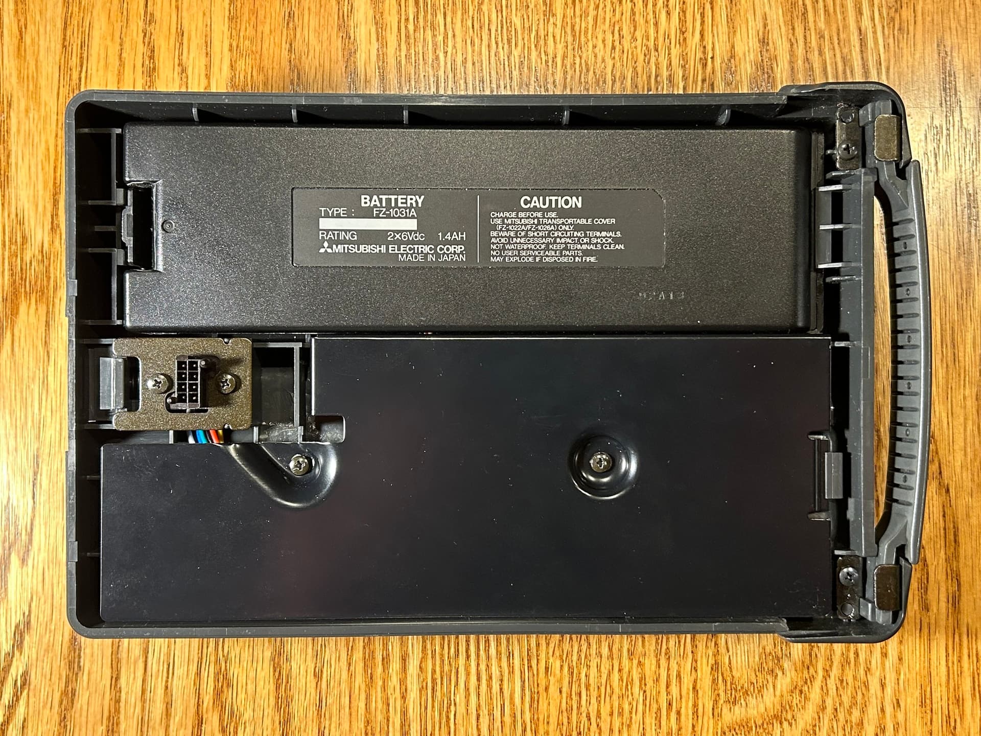
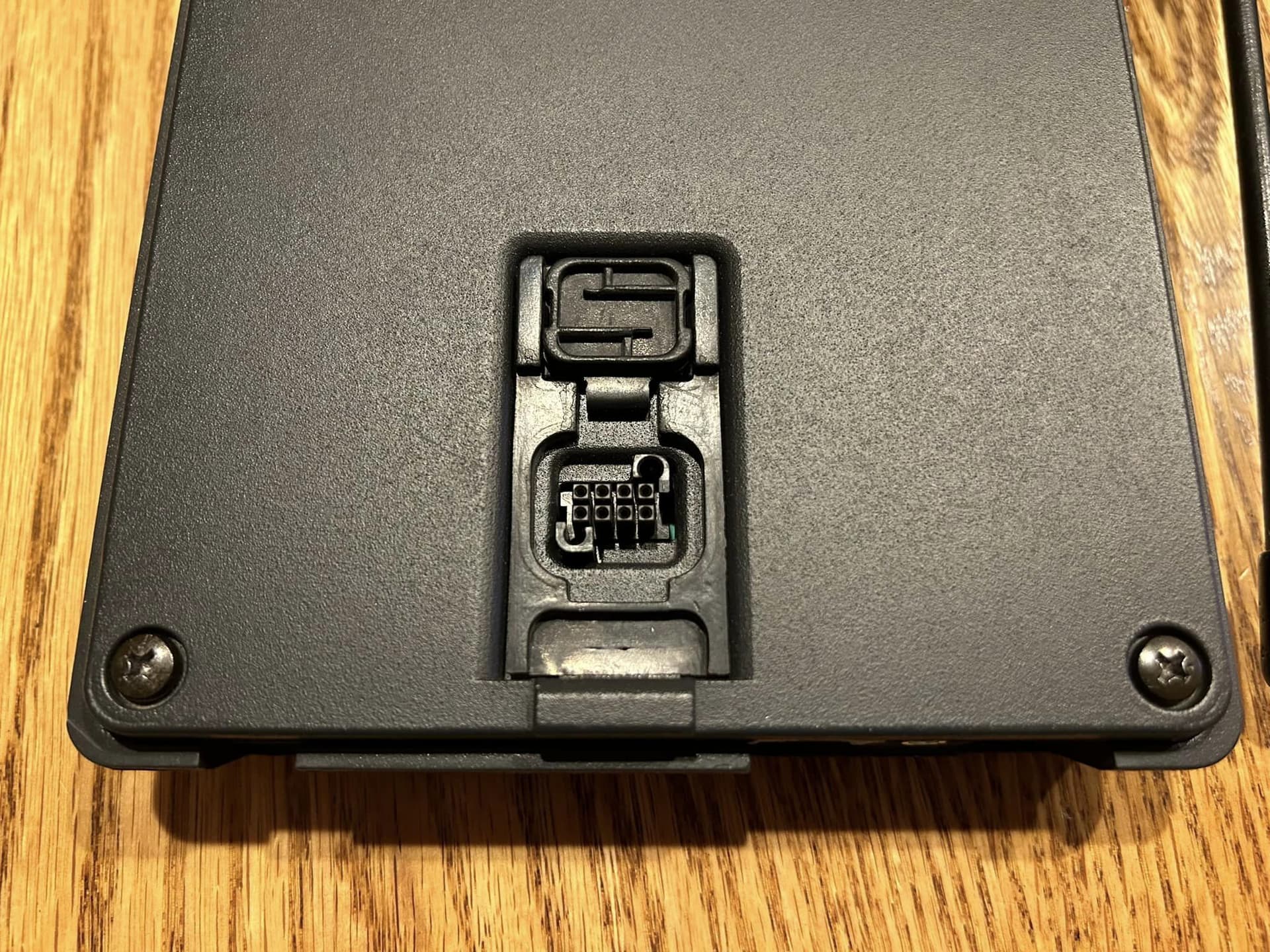
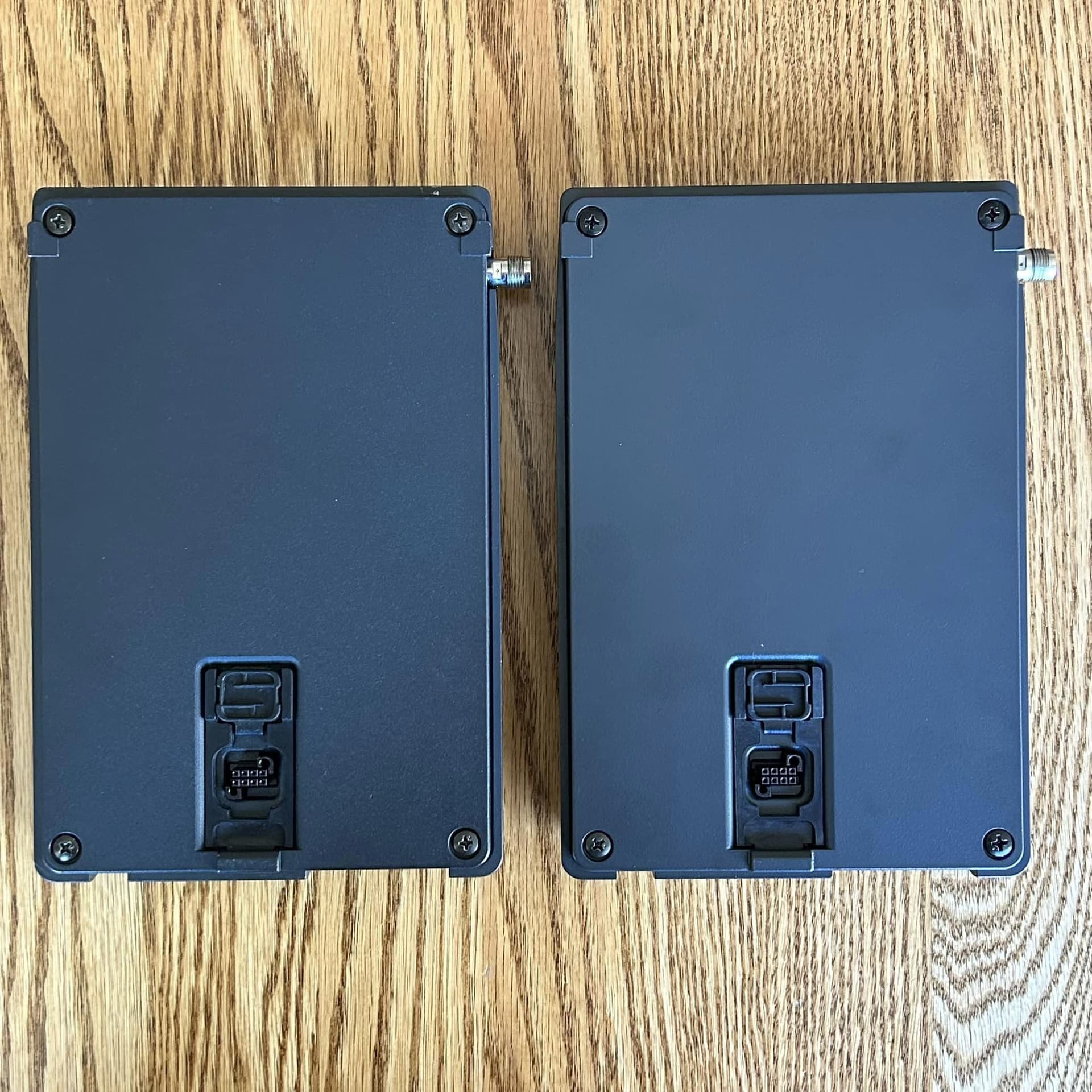
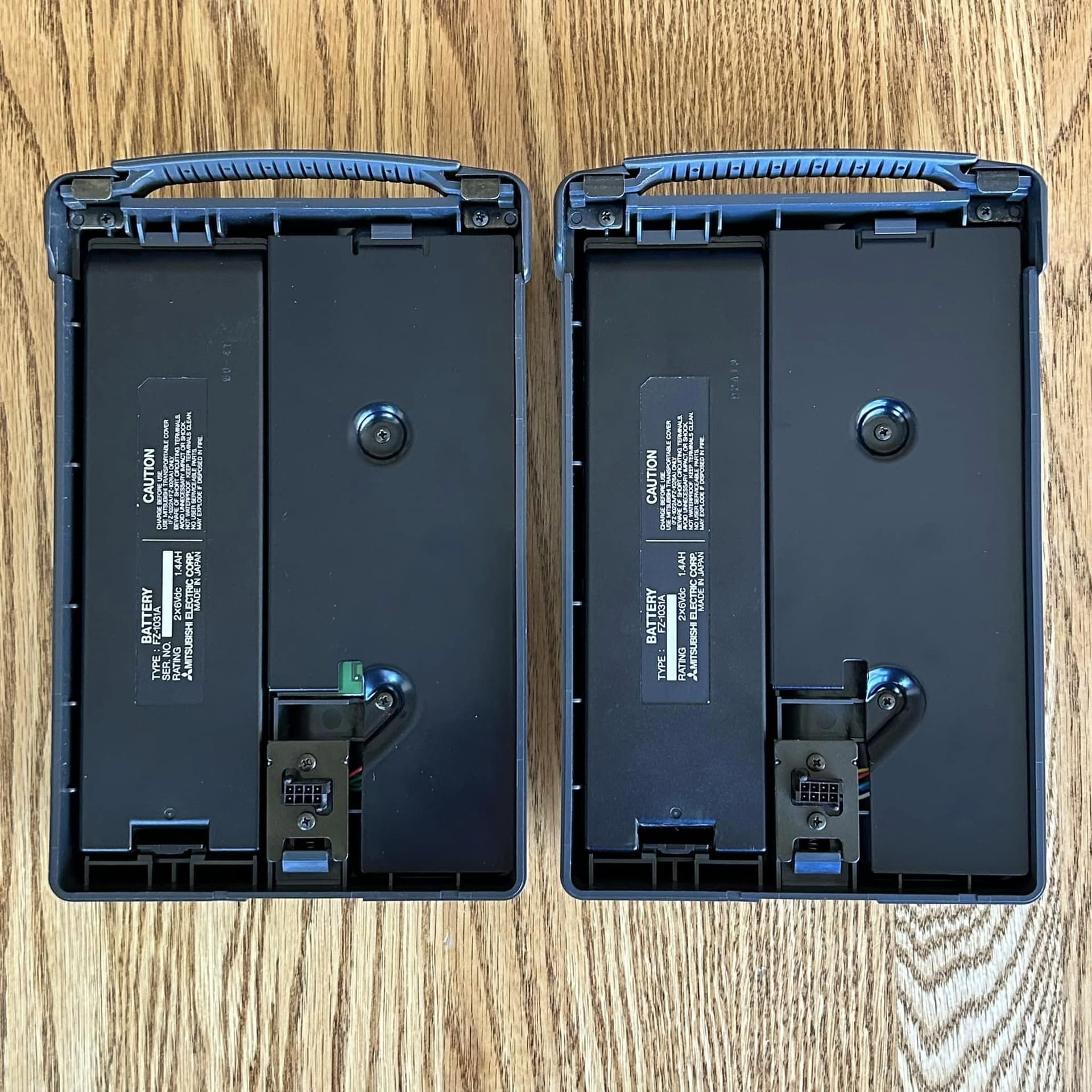
Here’s the bottom side of the plastic cover that holds the the original rechargeable NiCad battery pack and battery charging circuitry (under the black metal plate next to the battery). Theres an 8-pin connector that connects to the main transceiver board as you clip the cover into place. It’s a nice self-aligning connector that has been obsolete for many many years, so it’s impossible to buy more of these connectors:

Except I just lied to you a bit. There is no battery or battery charging circuitry in there.

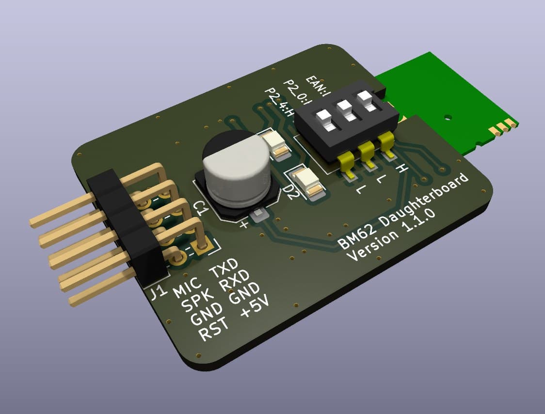
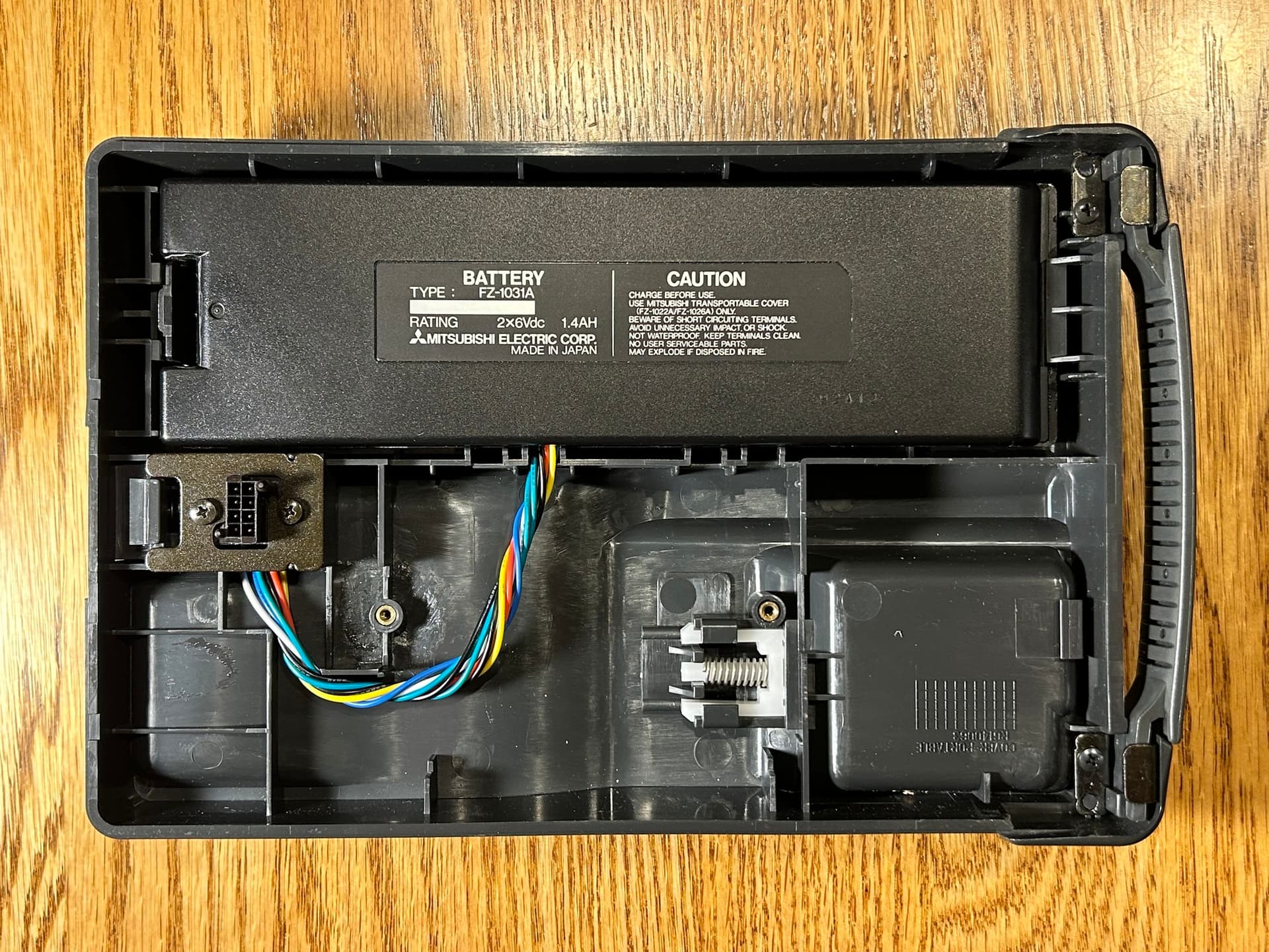
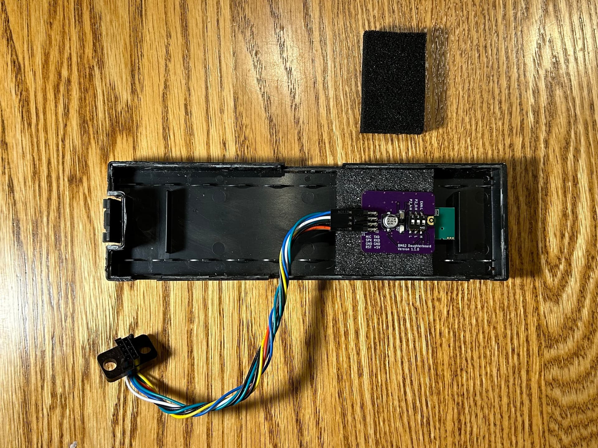
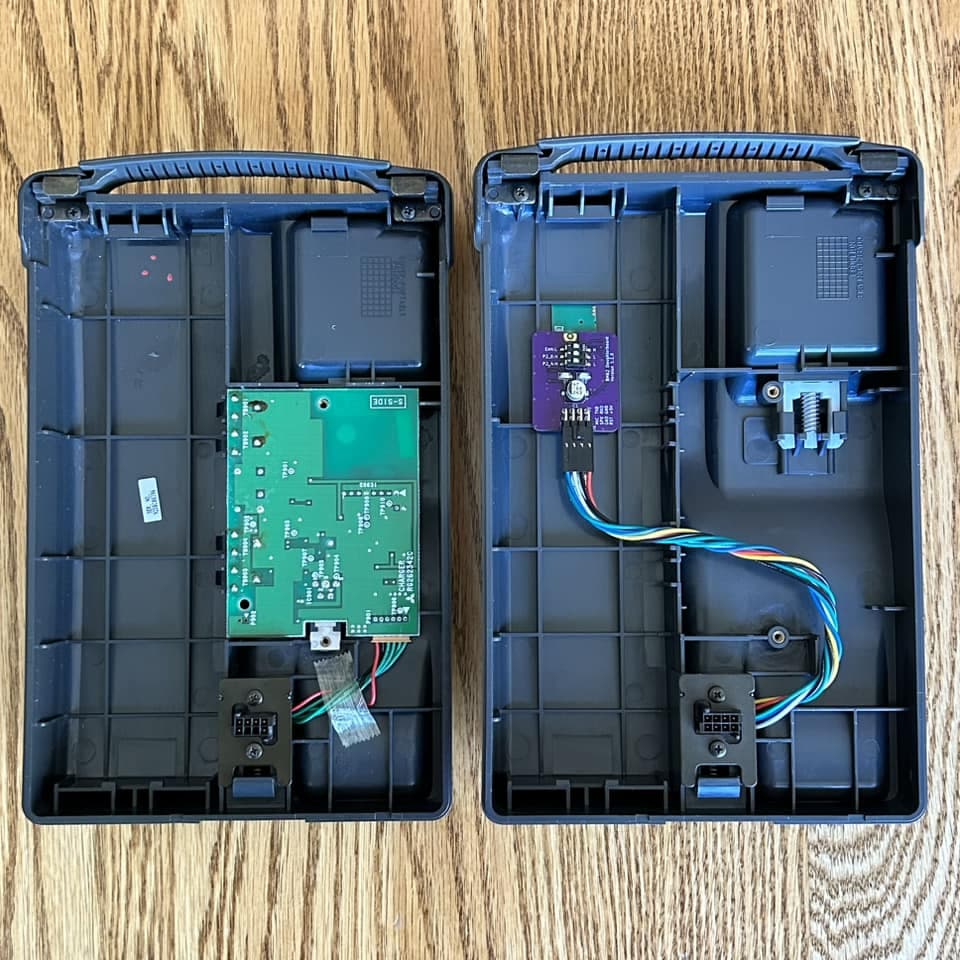
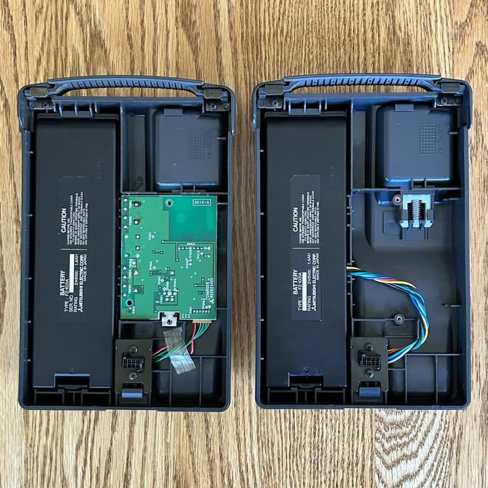
I gutted the useless 30-year-old NiCad battery pack so I could hide my Bluetooth module in there (securely sandwiched between two pieces of foam), de-pinned the original connector, and made a custom wiring harness for the Bluetooth module with the re-used original connector. The connector housing is no longer available, but the wire terminals it uses ARE still available!

Other than gutting the battery pack, no other non-reversible modification was done to the rest of the plastic cover, so it’s a pretty clean conversion.

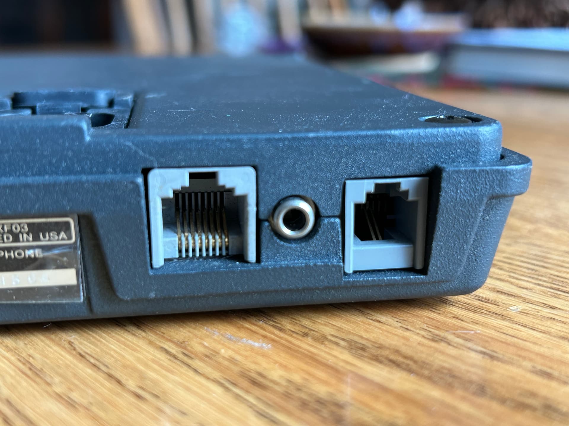
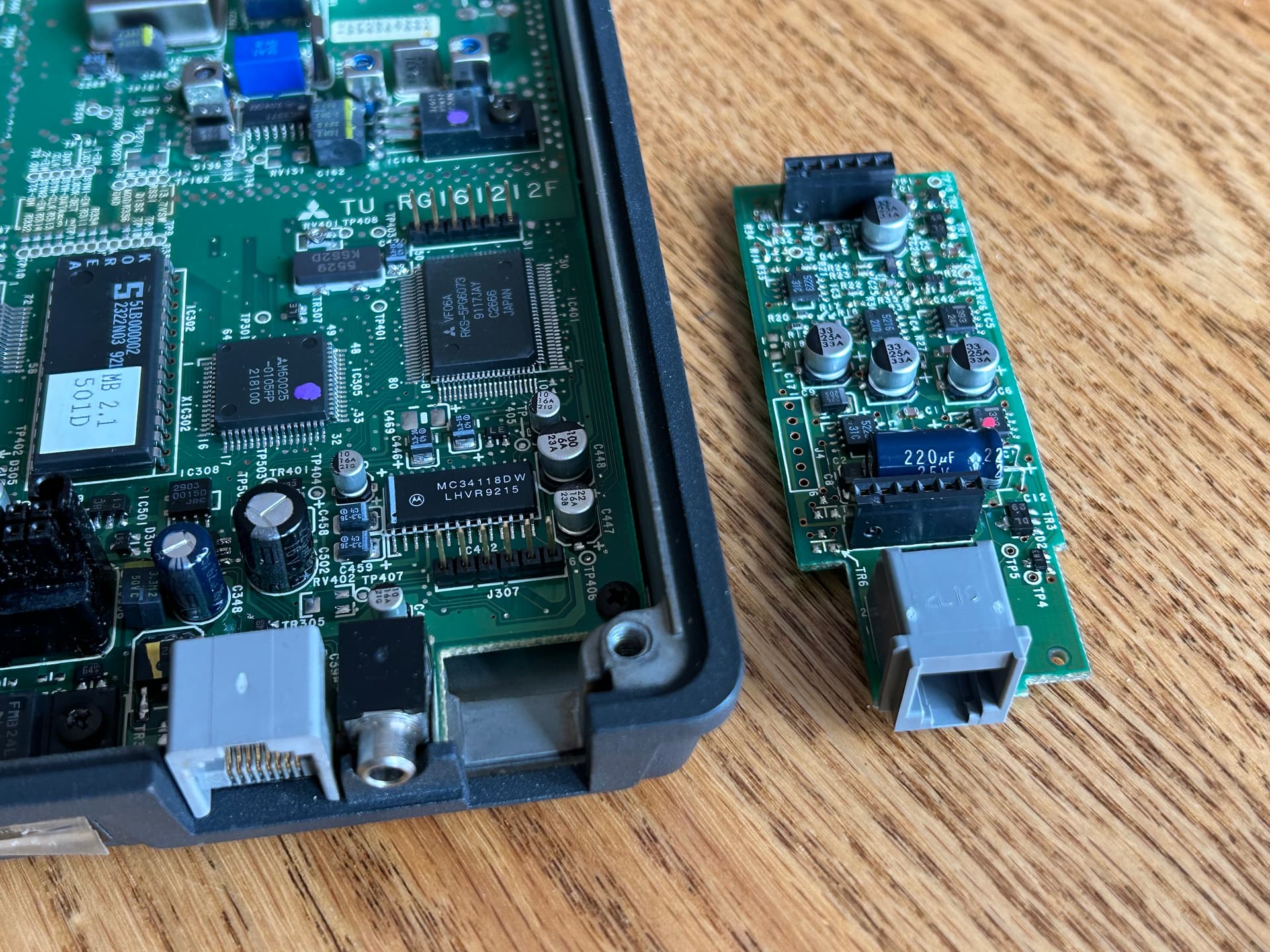
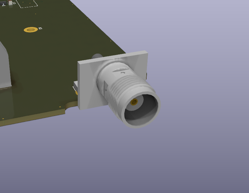
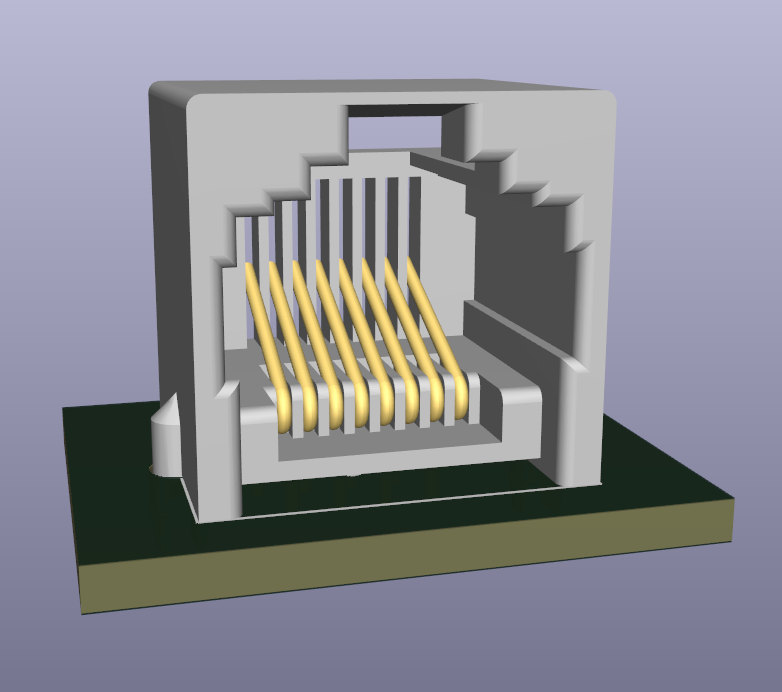
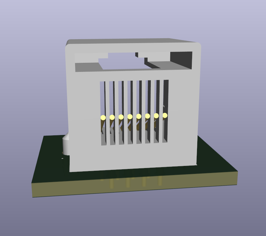
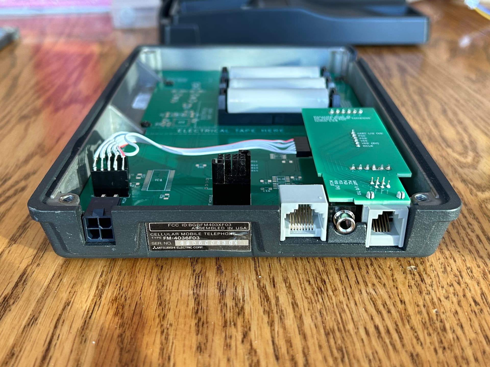
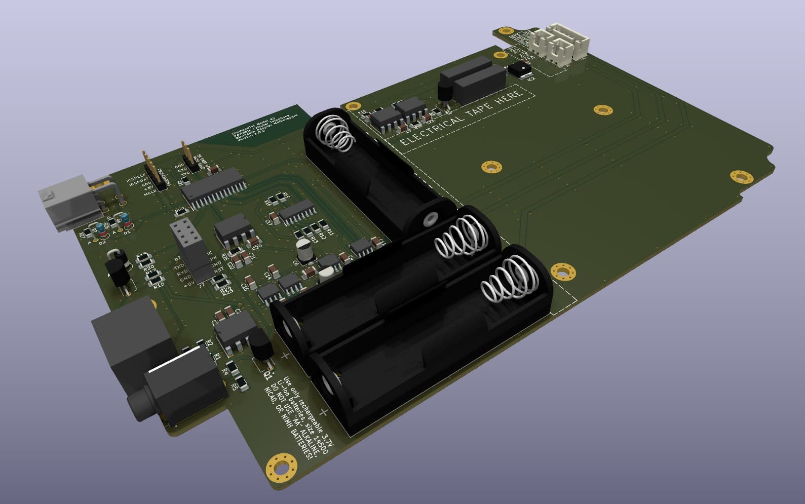
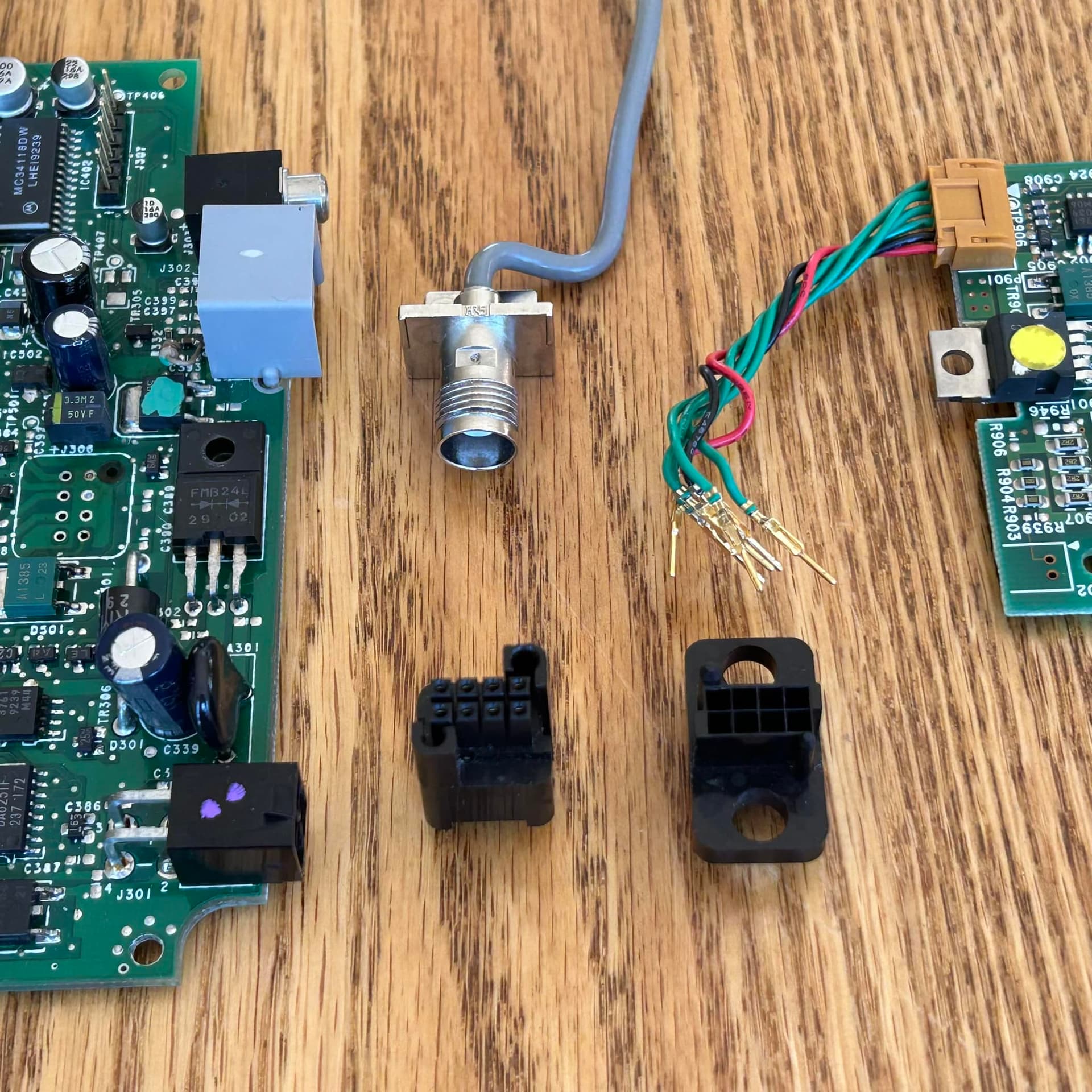
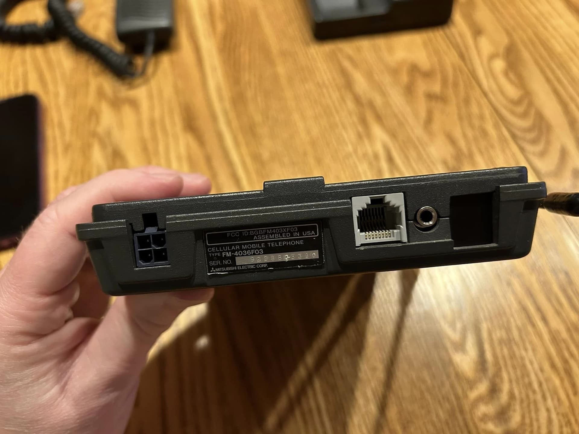
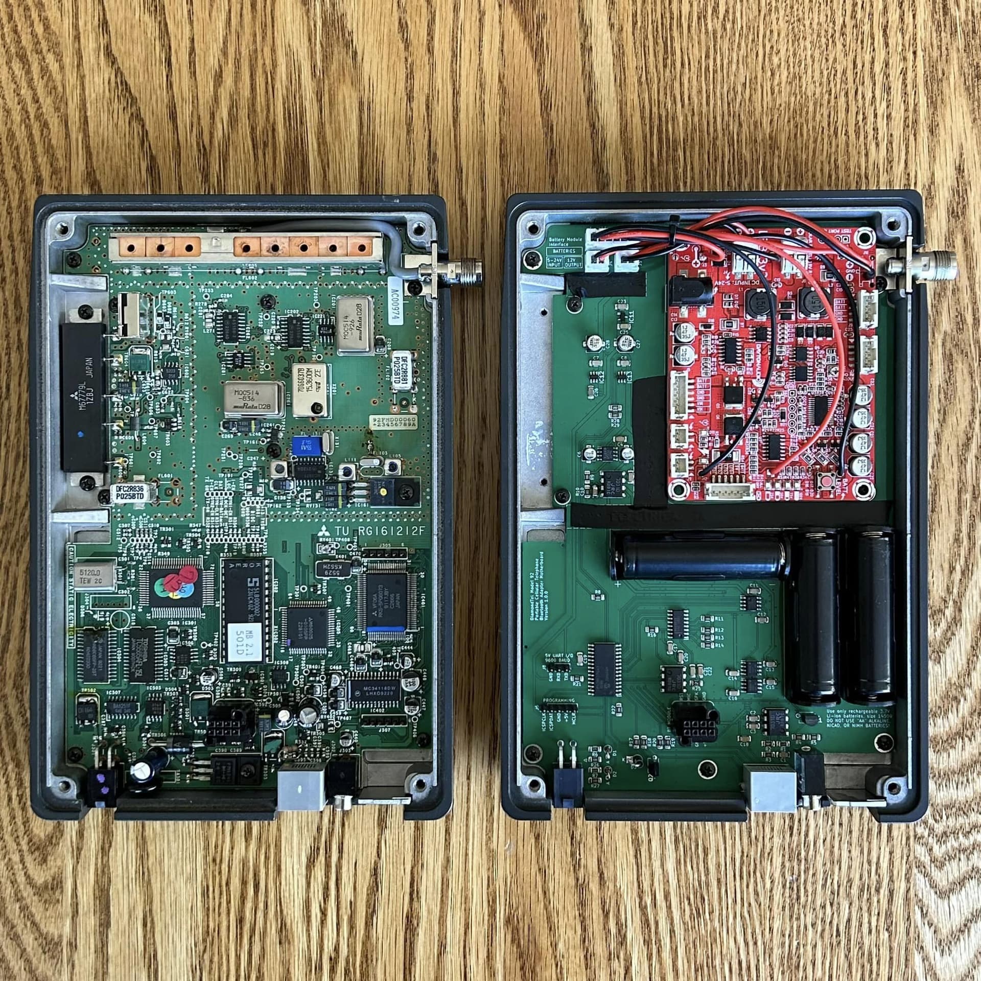
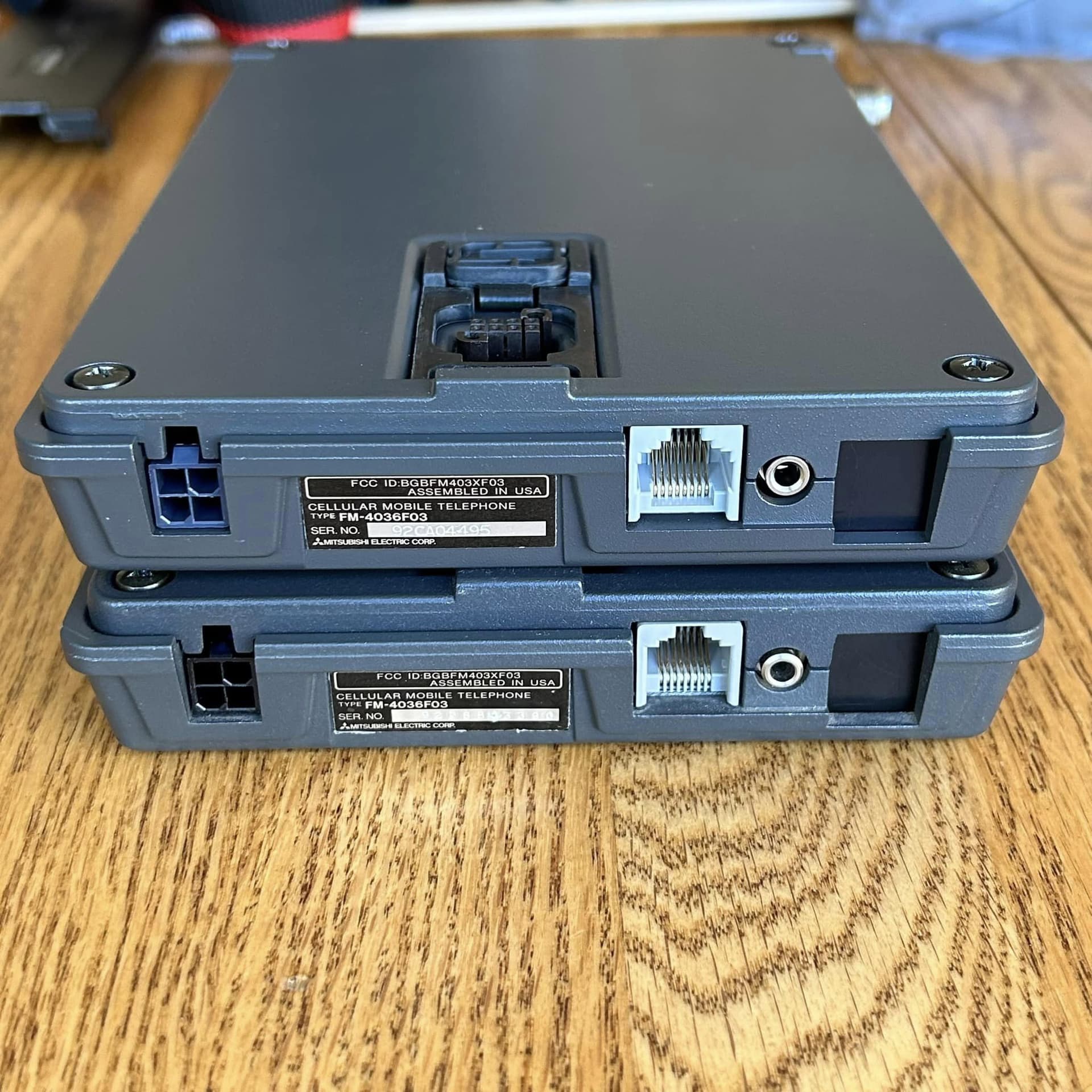
For the mating socket on the main transceiver circuit board, I have no choice but to de-solder it from the original car phone circuit board so I can re-use it on my custom PCB. In total, I am removing/reusing 3 components from the original car phone electronics:

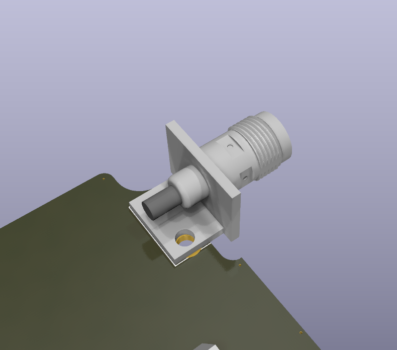
The 8-pin socket from the main transceiver board, the 8-pin connector from the battery charging circuit in the plastic cover, and the coax connector for the antenna. The antenna connector will not be used in my circuit, but I need to re-use it just so I can physically mount the original portable antenna for a complete original appearance.

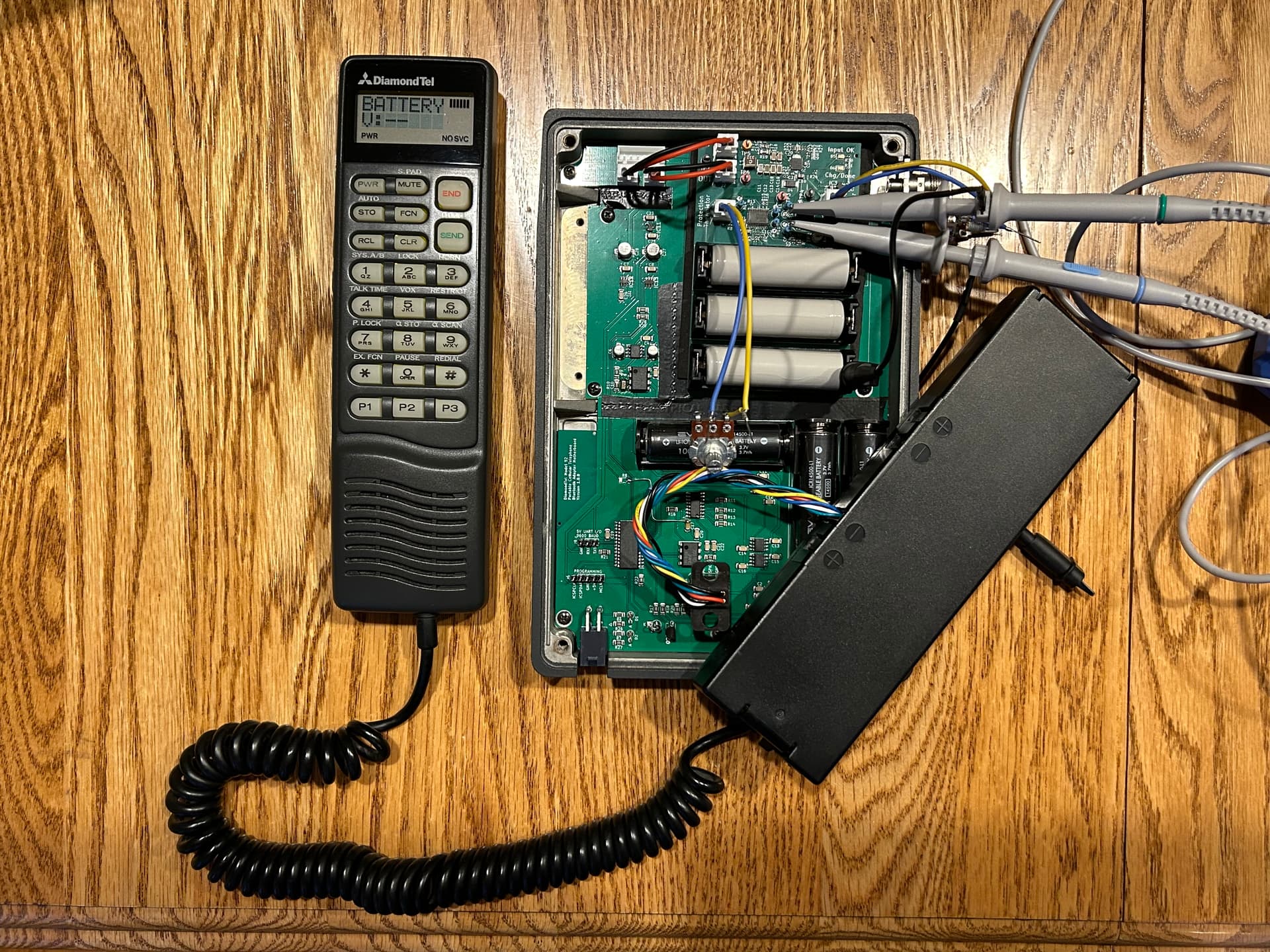
When I complete the main circuit board that mounts in the metal transceiver case, I will have a converted and fully functioning vintage car phone that looks 100% original from the outside, even if you remove the plastic cover :slight_smile:

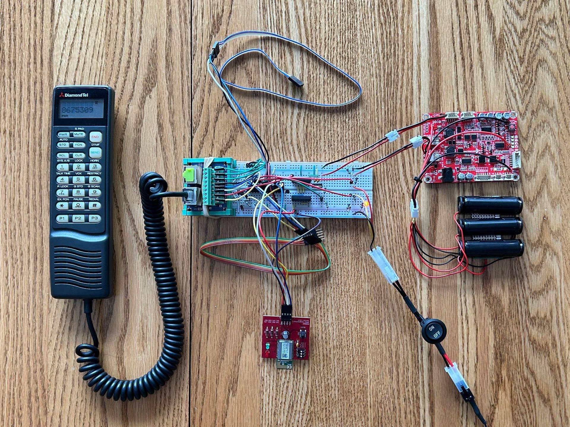
I’ve made a lot of progress on programming new behavior for managing power on/off functionality and monitoring battery voltage. Now that I’m in full control of power on/off behavior, I was able to re-implement original functionality where if you are in a call in your car when you turn your car off, the phone will remain on until the call ends :slight_smile:

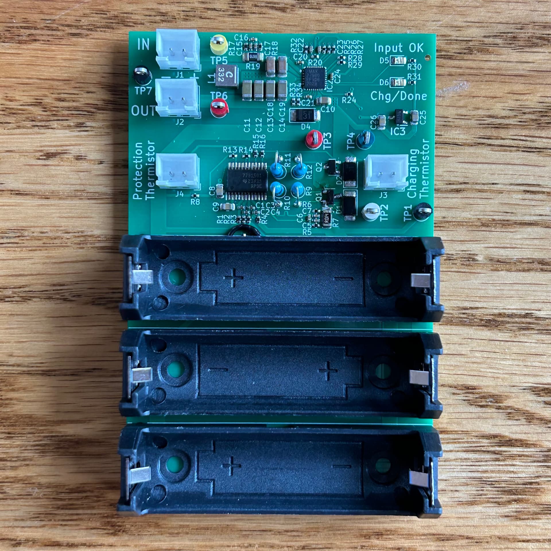
I’ve also been revising my circuit design to reduce power consumption. Batteries are expected to provide about 5 hours of active “talk time”, or about 18 hours of “standby time” (on, but not in a call). When turned “off”, I got current draw down to 0.05mA, which would take over 2.5 years to drain the 1100mAh batteries in a perfect world (but that 1100mAh probably isn’t “fully usable” in reality, batteries self-discharge over time too, and the battery charging module I’m using probably draws a small amount of current to monitor battery voltage too).

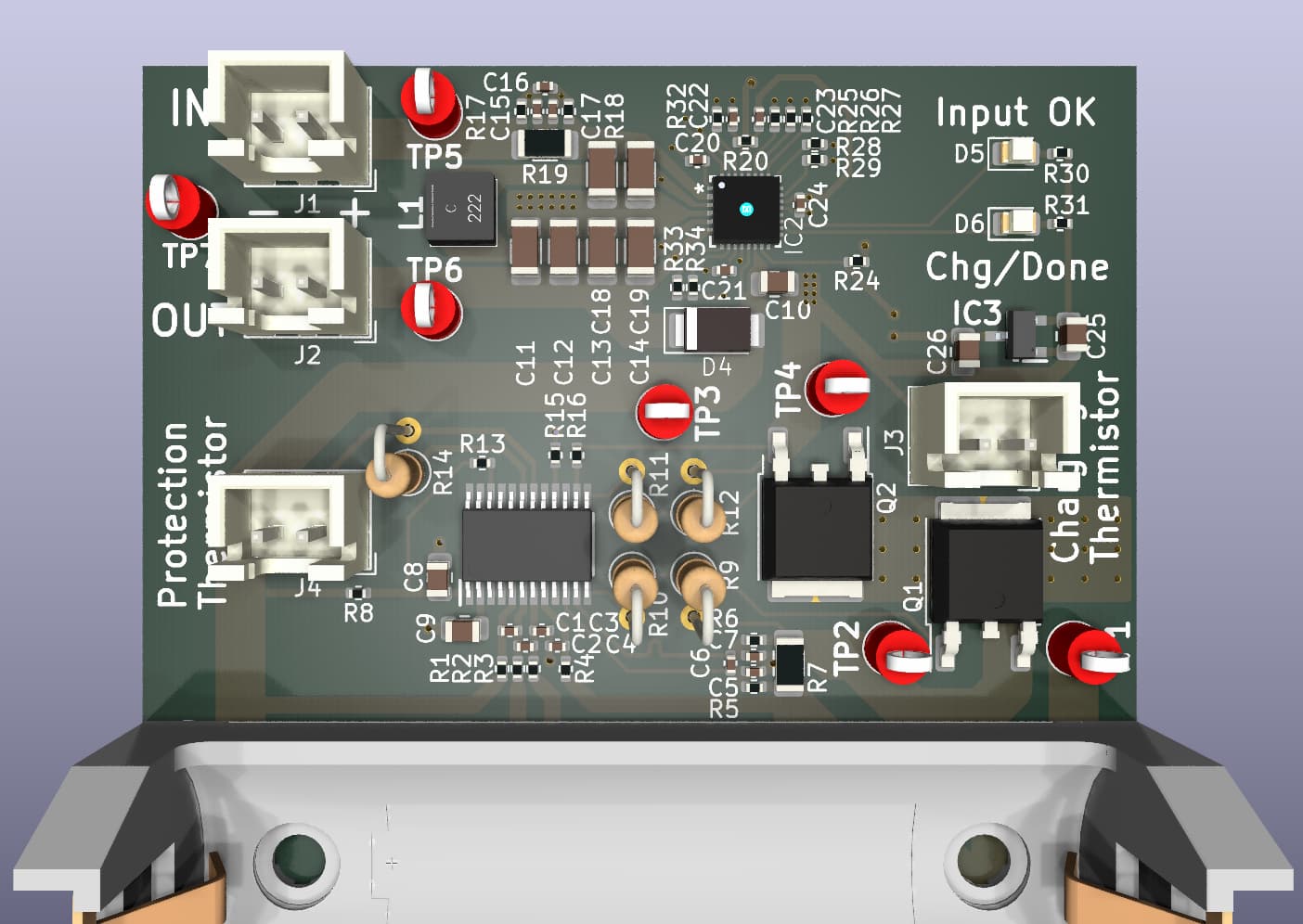
I’m hoping to get the main PCB produced in the next month or so. Fingers crossed that I didn’t make any stupid mistakes in my circuit schematic or PCB layout that prevent it from working :grimacing:

3 Likes

It’s alive!!!

Here’s my new custom PCB installed in the original car phone transceiver case. Everything fits perfectly, all the external connectors are perfectly aligned, and the circuit itself seems to be working as intended. I still need to do a lot more testing before I can declare it a complete success, but it’s looking good so far. Sound quality seems to be better than my previous external plug-n-play module prototype.

From the outside, it is practically indistinguishable from an original unmodified car phone. I’ll get a side-by-side comparison photo later.

1 Like

Here’s some side-by-side comparisons of an original car phone and one with my new Bluetooth adapter installed.

The main circuit board in the transceiver
Left: original
Right: modified

Transceiver with the lid installed
Left: original
Right: modified

Connections for external power supply, handset cord, and external microphone (for speakerphone)
Top: modified
Bottom: original

Inside the “transportable cover”
Left: original (battery charging circuit)
Right: modified (Bluetooth module)

My Bluetooth module hidden inside of the emptied out shell of an original battery pack
Left: original
Right: modified

Transportable cover fully assembled
Left: original
Right: modified

3 Likes

Amazing work :slight_smile: hats off to you

2 Likes

Here’s some video evidence of my new design working, and disassembly.

4 Likes

Sooooo…whats it gonna take ($, etc) to get you to do this to our model 92 phones? I have a NOS phone that I’d love to convert before putting it in the car. Your progress on this is amazing!

How did you get a NOS phone? I’ve only seen one before on eBay, and I bought it :slight_smile:.

It was complete with the “transportable kit”, and the universal vehicle install kit. But I still had to find the vehicle-specific hands-free integration components, which was very difficult.

I still have a few issues I want to try improving, then I’ll consider making a small batch. It won’t be cheap, because it’s still a prototype design that requires a lot of modification/assembly labor. I haven’t really worked on this project since my last post, and I don’t plan to work on it until winter. Next spring is probably the absolute earliest I might have something available, and it would probably be a conversion service rather than a kit.

Don’t wait for a conversion before installing it the car. Assuming that you have the vehicle install kit, the transceiver has a quick-release mounting plate, so you could easily take it out at any time for the conversion.

1 Like

I found mine on ebay as well and bought it. The VR4 previously had one, but the handpiece was missing, so we have been looking for one. Now we have it.

I’m making some progress again. One of the biggest issues with my latest design is that it relies on an off-the-shelf battery/power module (red board in the picture below) that needs to be modified and hackishly combined together with my custom electronics. It’s some pretty tedious labor, and it’s not the most reliable/robust design (multiple connectors involved in power delivery, risk of the board shifting around and shorting out, etc.).

Another issue is that the battery holders I used are pretty flimsy and do not create a reliable low-resistance contact with the batteries. I found some sturdier battery holders with better contacts, but they are a bit larger and would not fit anywhere inside the case, aside from the area currently occupied by the hacked-in red battery module.

So I’m working on solving both problems now by developing my own battery charging and power management circuitry that I can integrate directly into my custom PCB design. Here’s my first prototype as a standalone battery charging and power management module (so that I could invest less money into it at first and test the battery circuitry alone before integrating it with the rest of the project):

That is a battery charger, cell balancer, battery protection (under/over-voltage protection, over-current protection, under/over-temperature protection), and power path management (supplies output power seamlessly from either the batteries, or from external power when available, while charging the batteries). It also includes the upgraded battery holders, and this entire circuit (including battery holders) should fit in the same area as the hacked-in red board.

I’m working with some tiny components, like the battery charging IC that is only 4x4 mm, that are also sensitive to proper PCB layout for correct functioning, so this isn’t something I can test on a breadboard first. I have to go straight to having custom PCBs made so that I can start testing.

Unfortunately, my first attempt failed. I did not understand how to analyze MOSFET specs, and chose MOSFETs that were much too small and would fry with very low amounts of current. So I am currently waiting for my second prototype with much larger MOSFETs that should handle the current of these batteries better:

If I can get this battery/power management stuff working well, then it should become practical to start offering conversions… as long as people are willing to accept a bit of background noise in the audio that I’m not sure how to solve yet.

While I was waiting for my first battery/power management prototype, I started a side quest to make use of some extra space that is freed up by moving the batteries…

The original car phone had support for an optional “data port” for connecting to fax machines and dial-up modems. It’s a separate small circuit board that connects to the main circuit board that adds an RJ11 (telephone) jack:

I’m making a replica (in shape/size) of that extra add-on board, and I even found the exact same part for the RJ11 jack is still available. But I’m upgrading to a 6-contact RJ12 port. I’ll be using this for programming and debugging of the microcontroller without needing to open up the case.

Here’s some 3D renders of my programming board add-on board, and how it will look together with the main board.

The pin headers used to mount the programming port to the main board are structural only in my design, because the actual connections for programming and console debugging output are on the opposite side of the board. I’ll have to make a custom wiring harness to connect them together. I may consider trying to reorganize my PCB layout in the future so that I can eliminate this wired connection.

I’m excited to have easy access to programming/debugging through a port that looks 100% original. I ordered some of these programming port boards and the main board (bare boards with no components installed) so that I can install the ports, battery holders, and pin headers to confirm physical fitment of everything. Ordering bare boards is pretty cheap, especially if you combine multiple different boards in one order to combine shipping costs.

And yet another side quest helped produce the 3D renders in the previous post: I’m learning basic 3D CAD modelling with “onshape” (free online software). Some of the components I’m using in my PCB design either have no 3D models available at all online, or the models available online are pretty awful.

Here’s the models I’ve made so far…

The coax antenna port. This is a proprietary part that can’t be found online at all:

The connector that sticks up out of the transceiver case and mates with a connector on the “portable cover” (originally used to connect to battery and battery charging circuitry in the original phone; I use it to connect to the Bluetooth module). This is an obsolete part with extremely limited info available online (basically just that it exists but is obsolete):

And this is the RJ45 port that the handset cord plugs into:

There is a 3D model of that last part available online, but it’s awful:

I think my version is much better :slight_smile:

None of this is really necessary to successfully design the circuit or PCB layout, but it is much more pleasing to see a somewhat accurate 3D render of the circuit board with all the components populated.

4 Likes

Amazing work. True passion.

1 Like

Maybe borderline unhealthy hyper-fixation/obsession :laughing:

Here’s a demo of how the original car phone can beep the car’s horn to alert you to an incoming call when you are away from your car.

Could you imagine sitting in a restaurant eating lunch while listening for your car horn, then running out to answer an important call?

I’m considering replicating this feature in my Bluetooth conversion. It will be a pretty useless novelty demo of how old car phone tech worked. With my conversion, you’ll have your modern cell phone with you when you go away from your car anyway (no need to go back to the car to answer the call), and you would have to stay within about 20 feet of the car to maintain the Bluetooth connection. So there’s absolutely no practical use for this. But I still want to do it.

Technically, it is very simple: just a transistor used as a low-side switch for the horn relay circuit in the car. I have one unused pin on my MCU that I could use to trigger a transistor, and I found the specs of the (obsolete) transistor in the original car phone that I can use as reference to confidently select a suitable equivalent.

The only downside is that the factory car phone wiring in the 3000GT does not include the necessary wired connection between the car phone and the car horn relay, so I would have to dismantle the interior to run a wire from the trunk to the dashboard area, and splice it into original wiring. I’m conflicted between keeping my car original, with only the originally-supported car phone integration, versus adding a custom wired connection to fully take advantage of an original feature of the car phone. I’ll probably at least update the hardware design to support it, then I can decide later whether to follow through with the software implementation and custom wiring in my car.

My updated battery/power management circuit is working! I did a lot of testing with a power supply and electric load, and have moved on to testing it with my car phone Bluetooth adapter.

The larger MOSFETs seemed to solve all my problems. I was able to draw over 2 amps for an extended period of time without issues (way more amperage than my car phone will ever draw, around 250-300mA max). Nothing got noticeably hot to the touch.

I was also able to successfully test all the various safety features (over-current, under-voltage, over/under-temperature). Most importantly, I was able to confirm that when connected to the car phone circuit, an under-voltage fault can be recovered by simply connecting external power (no “load removal” required).

I also got new PCBs to test the fitment of the new battery holders in their new location, and the new programming port. Everything seems to fit well, except I think I need to move the programming port to the right about half a millimeter.

Here’s a comparison of my custom PCB/connectors (top) to an original car phone with the optional data port installed (bottom):

And here’s my custom RJ12 programming/debugging cable connected to a PICKIT4 and a USB/UART adapter (for console logging output to a terminal on a PC), and plugged into the programming port:

Next up is many hours of transferring the battery/power management circuit design over to my main car phone motherboard design, reorganize some things (using the extra space freed up by moving the batteries, add support for the horn beeping circuitry, and make some other improvements before I can place an order for new PCBs.

I’m going to try some major reorganization to position the MCU near the programming port so I can eliminate the need for a ribbon cable.

4 Likes