Hi
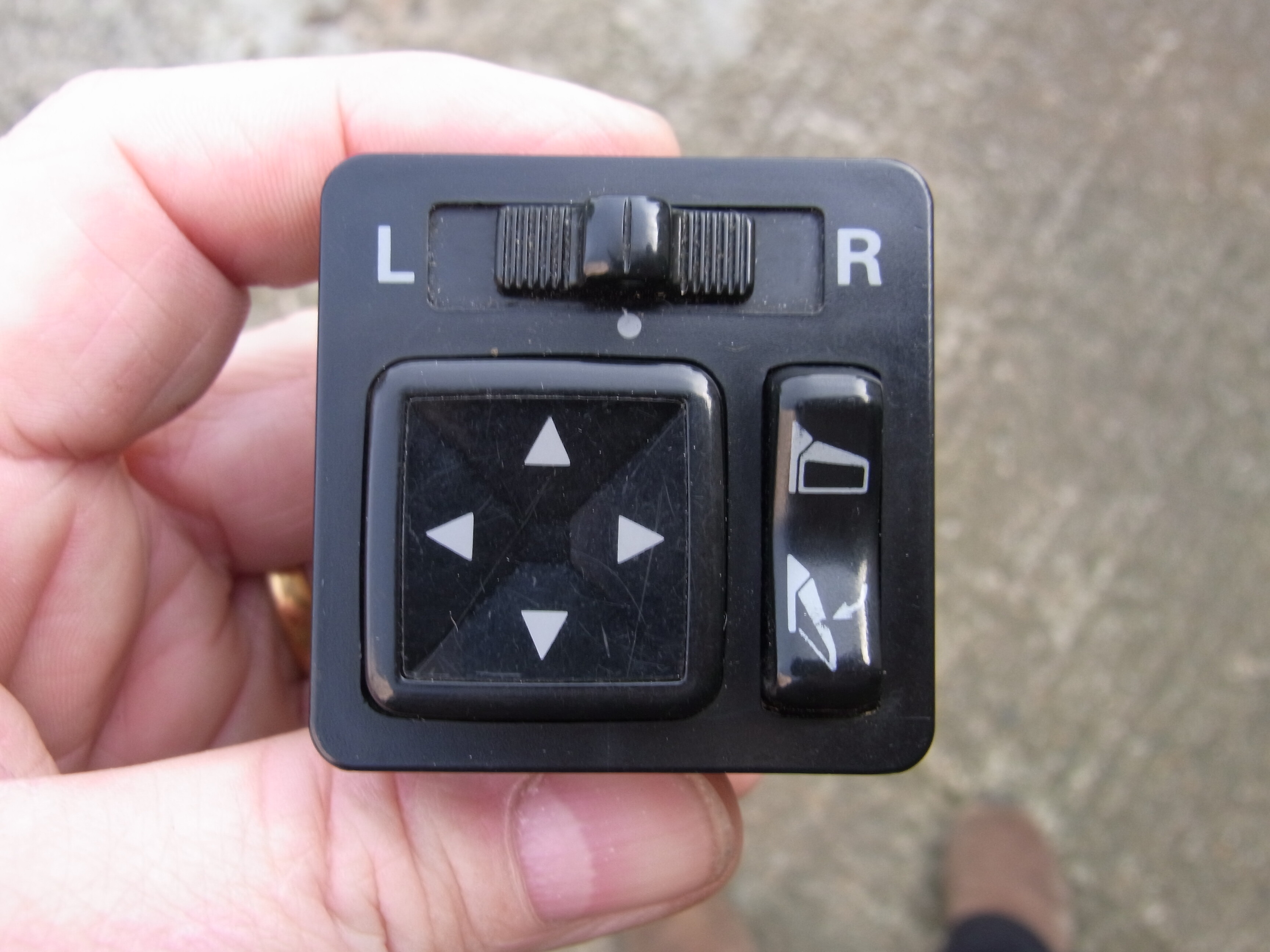
My Electric Mirror switch no longer Lights up with the sidelights,
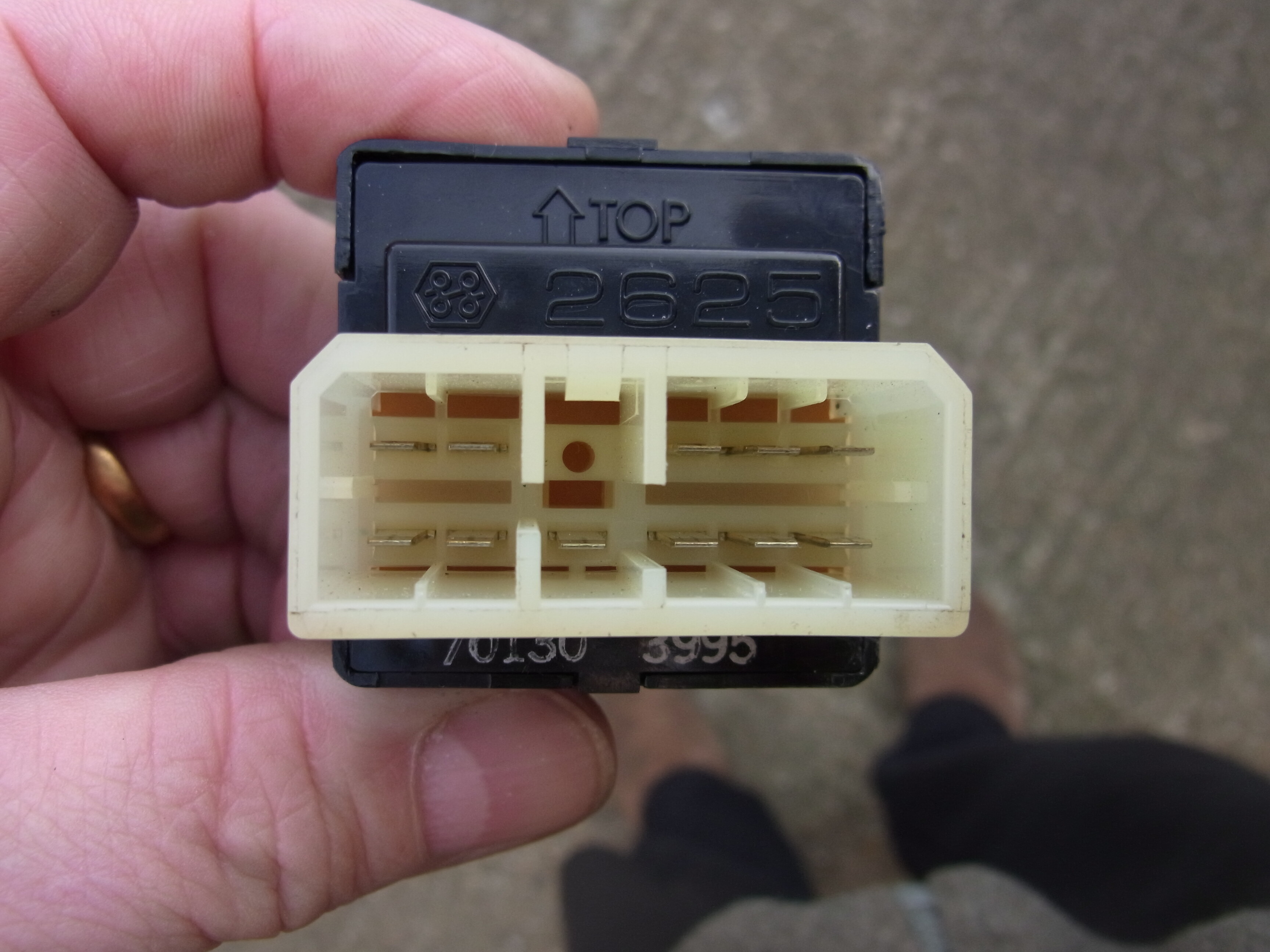
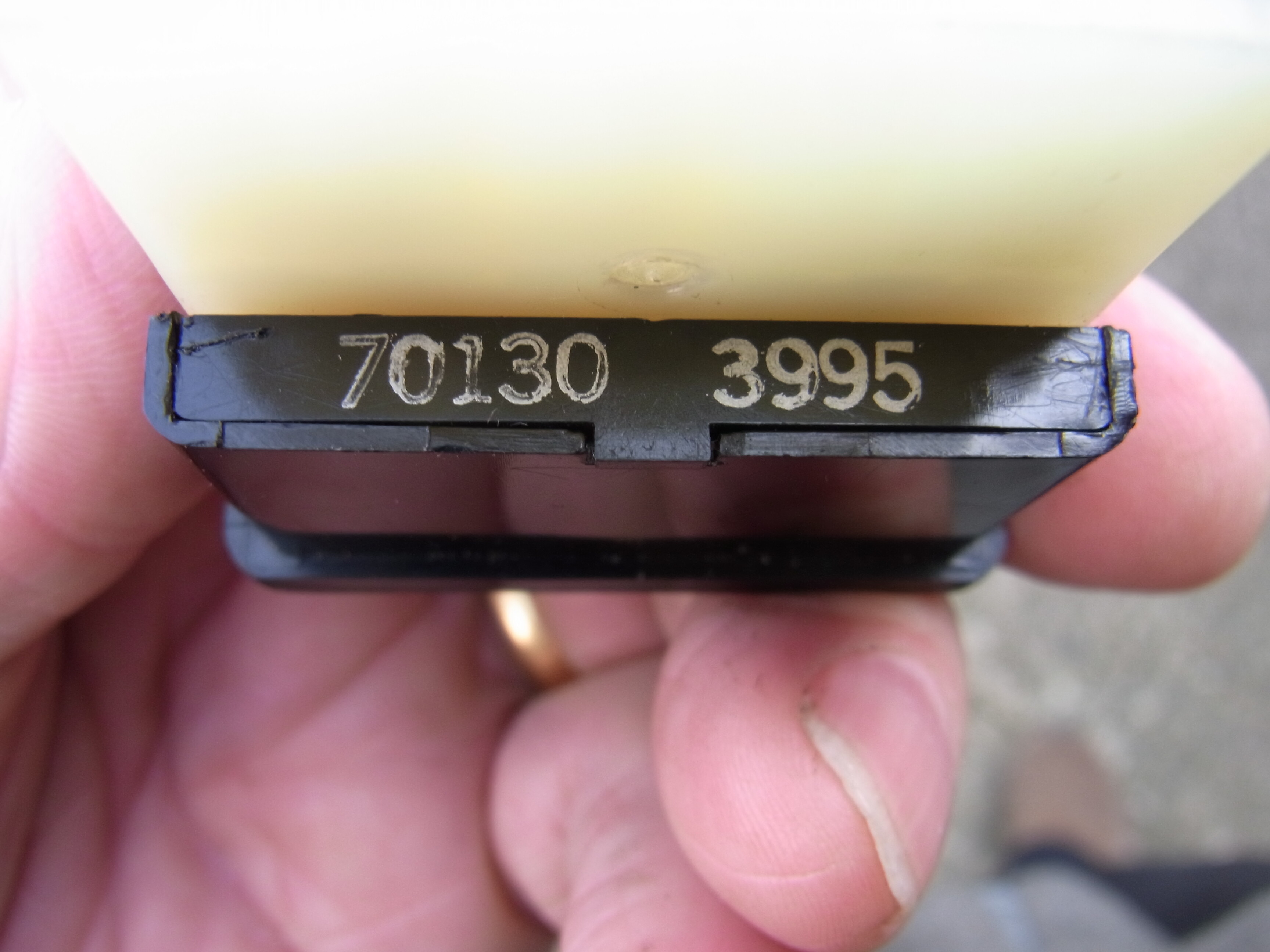
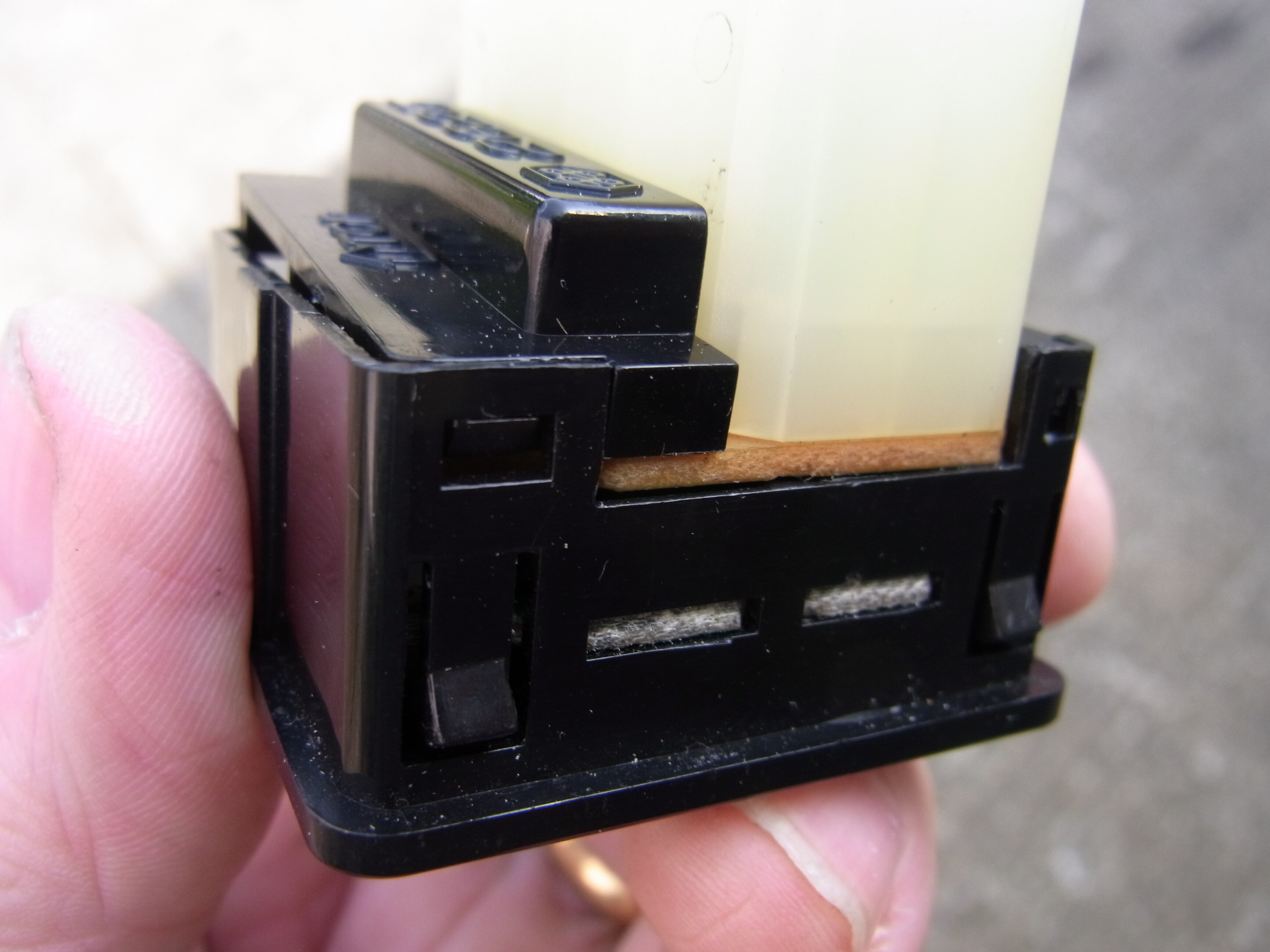
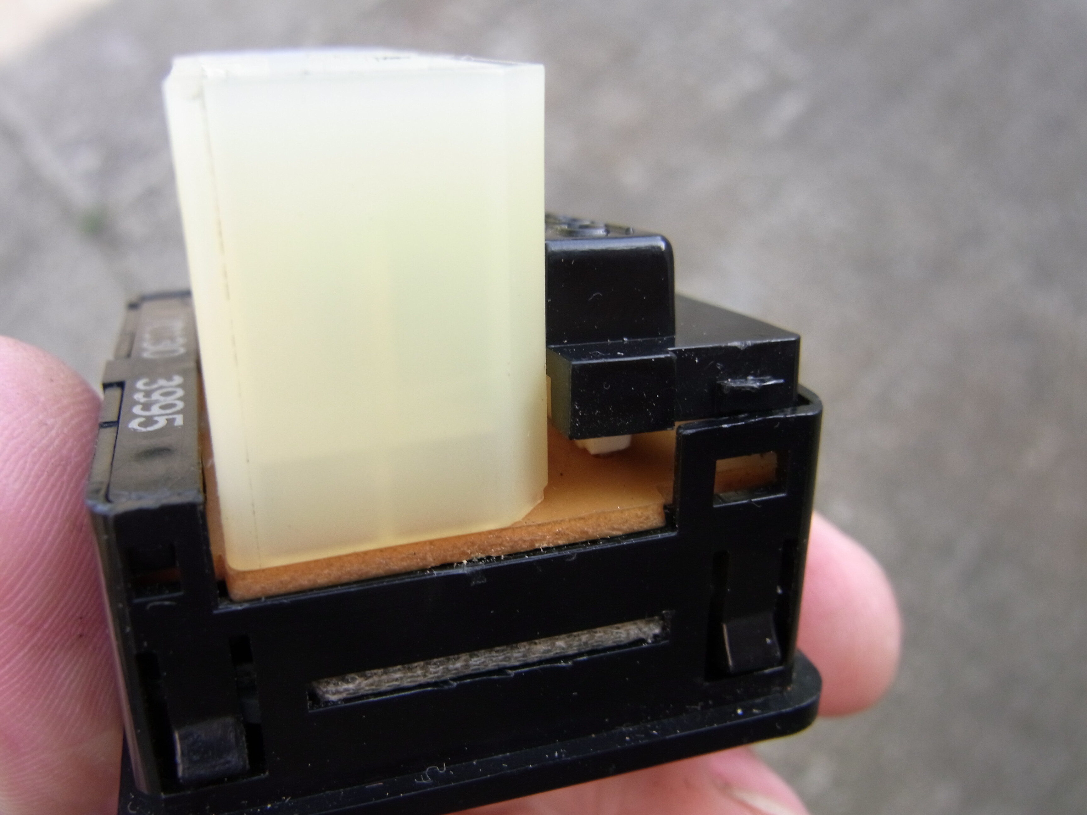
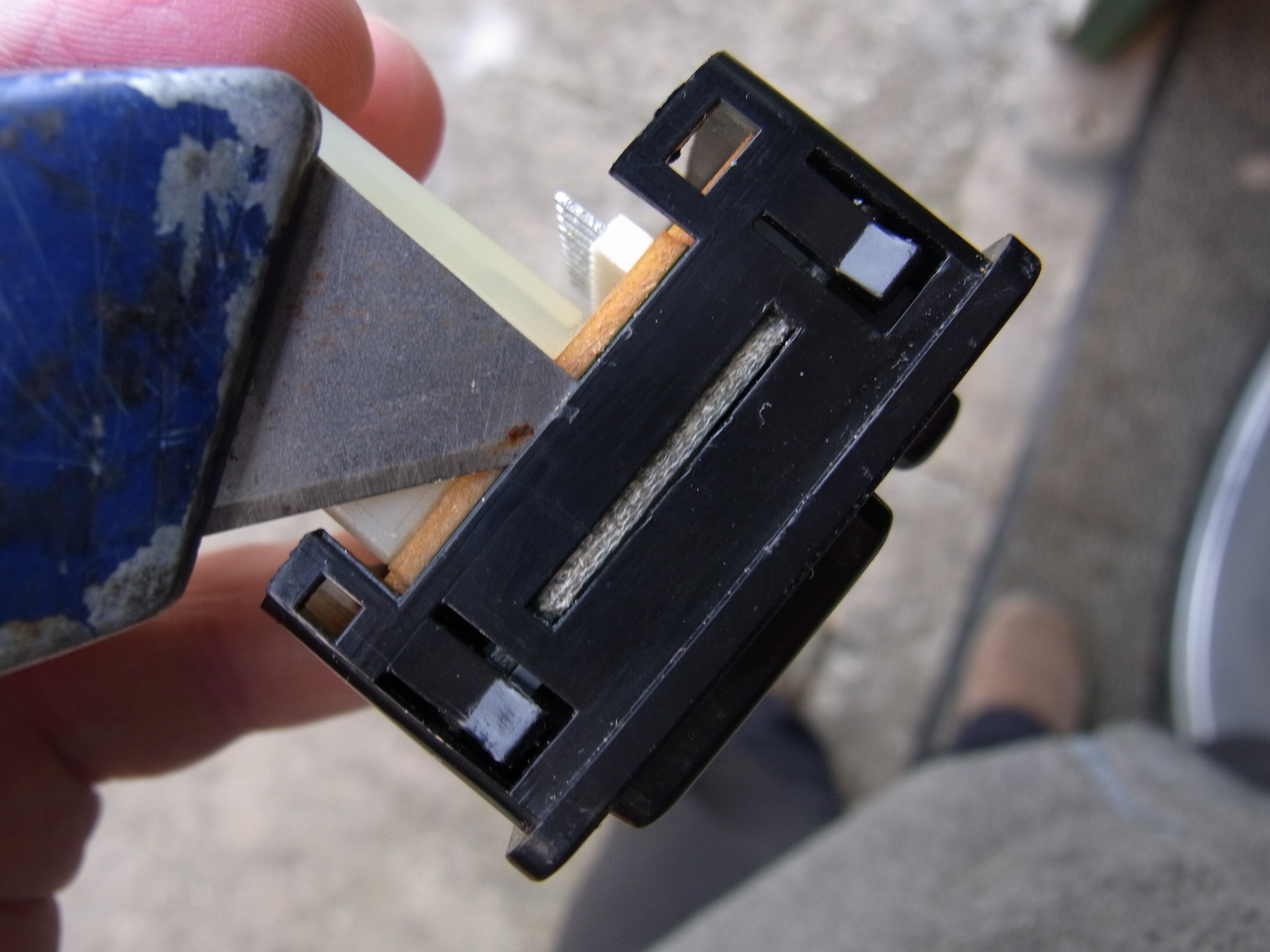
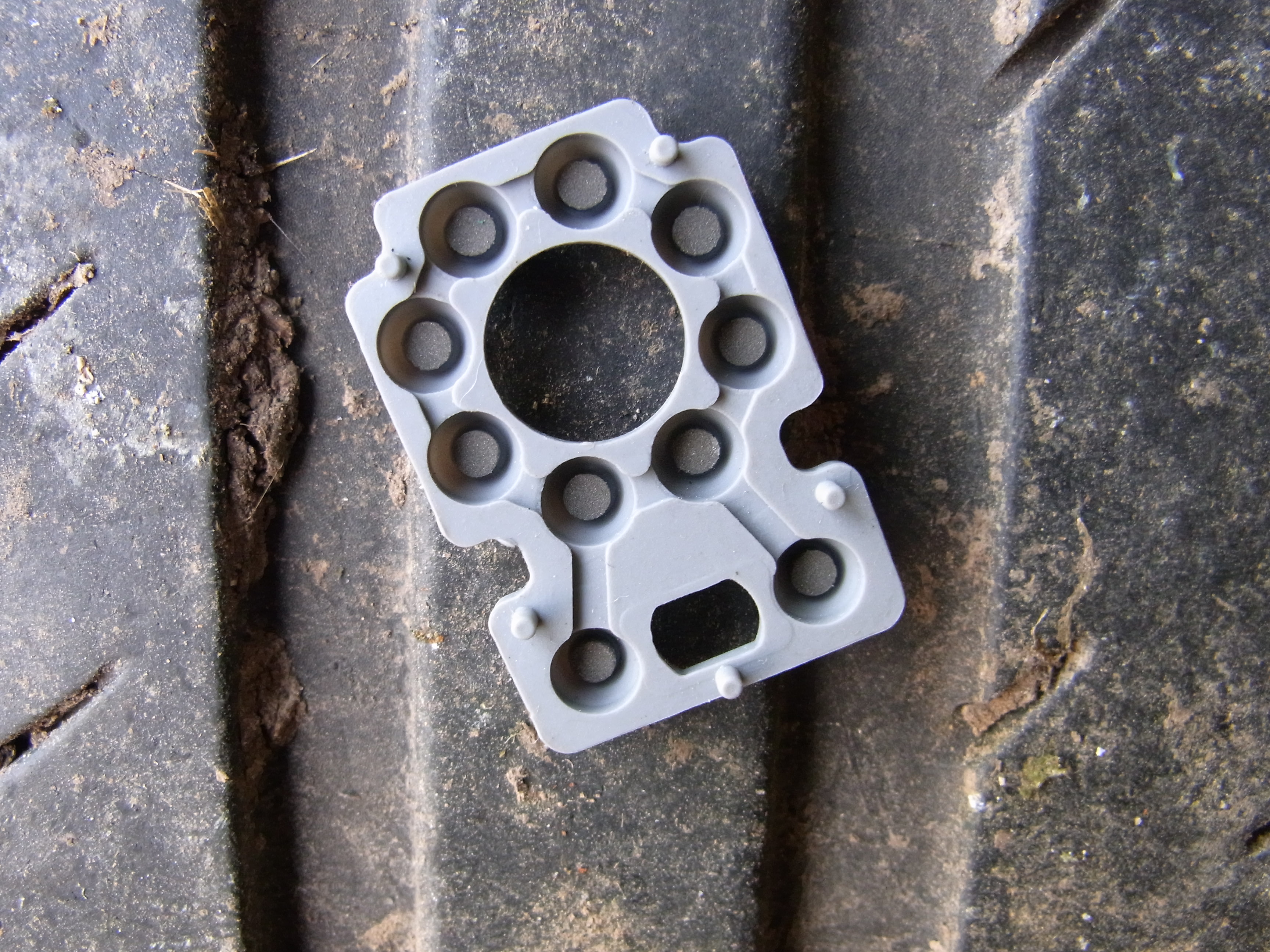
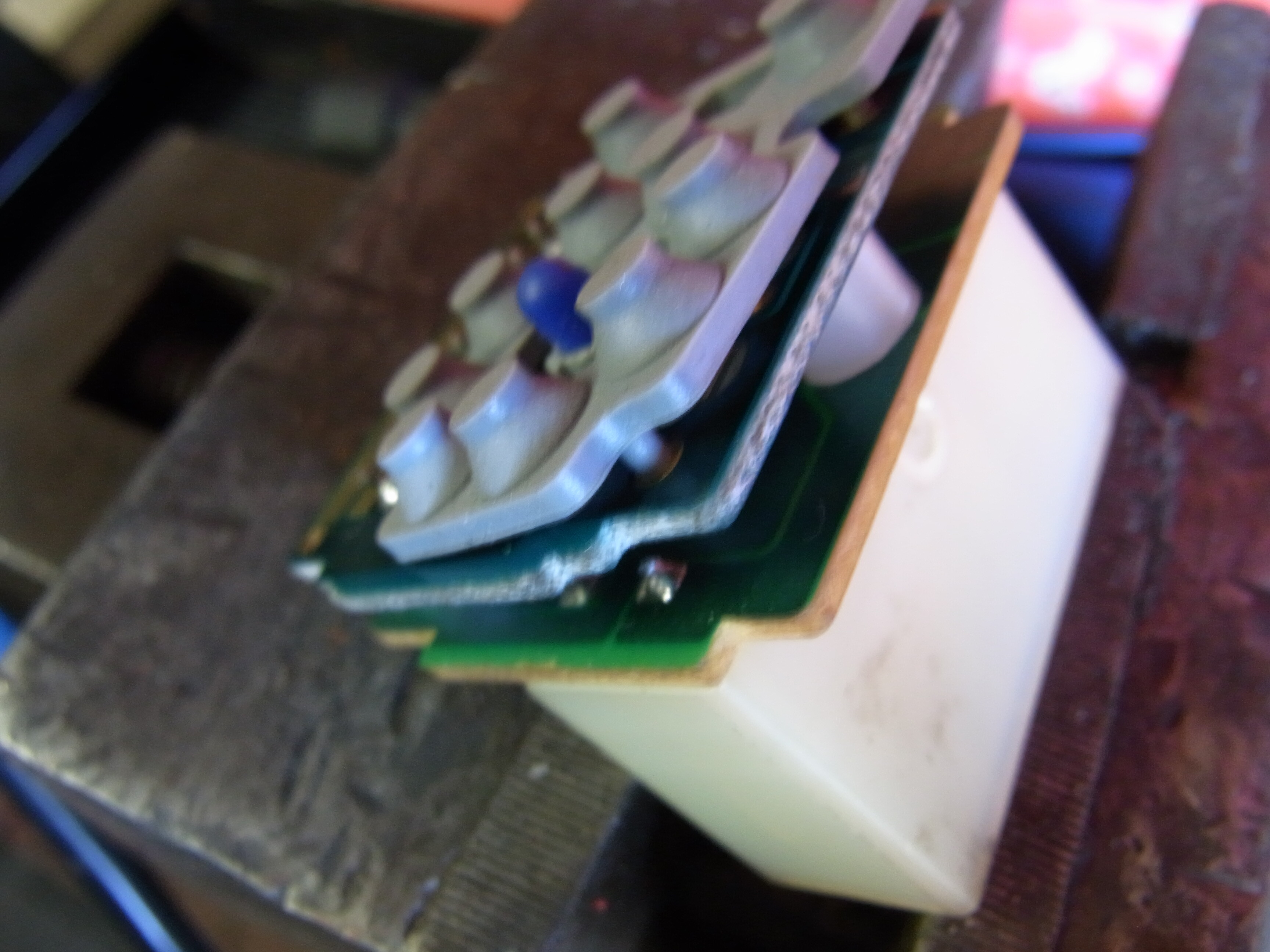
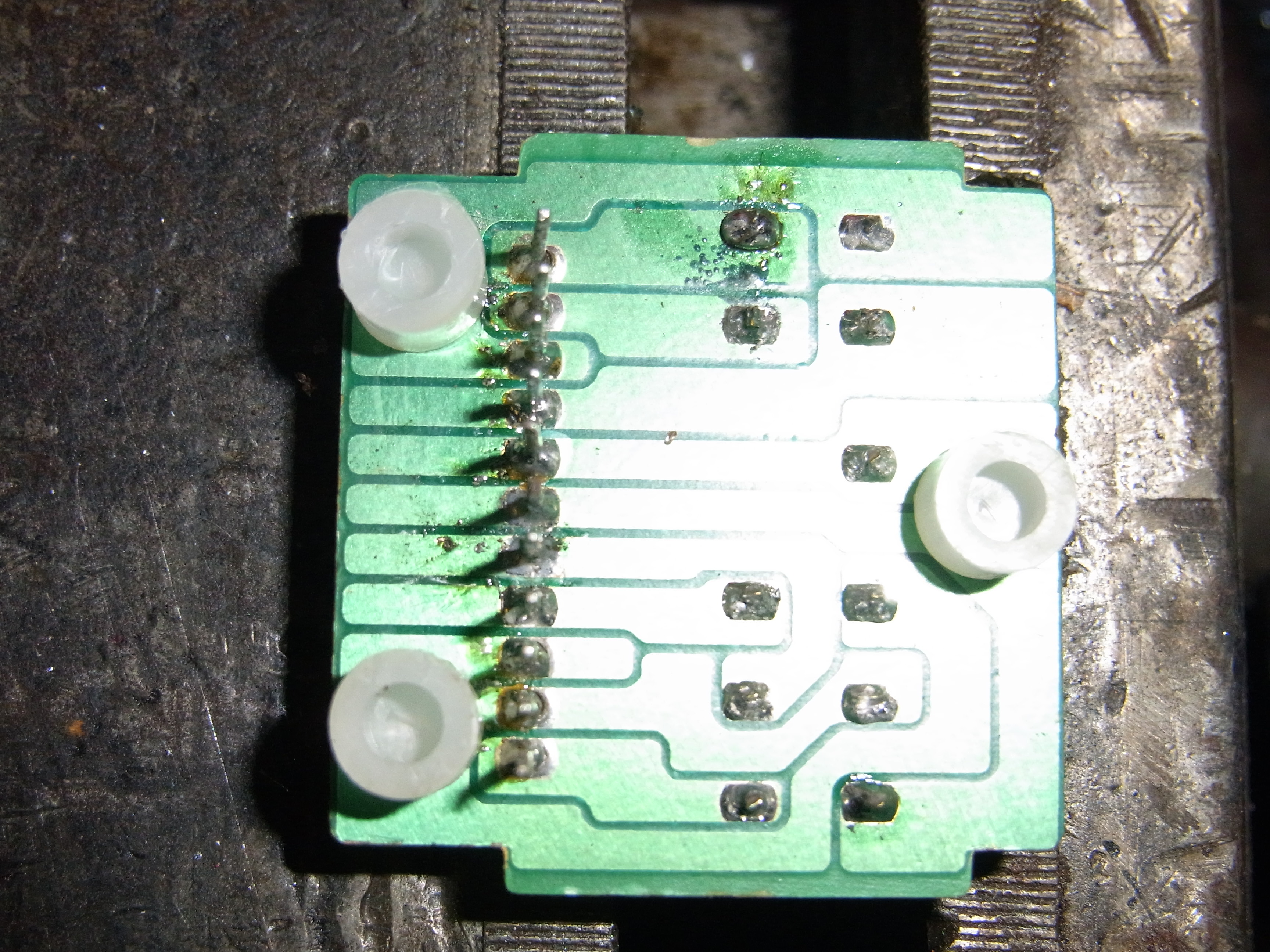
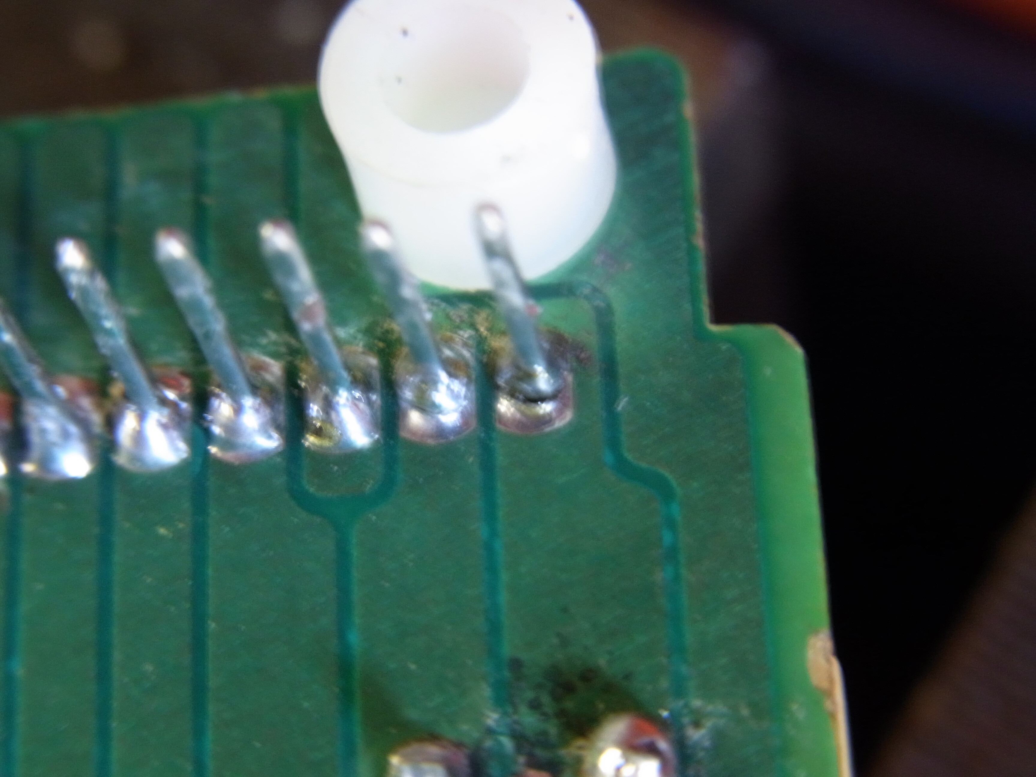
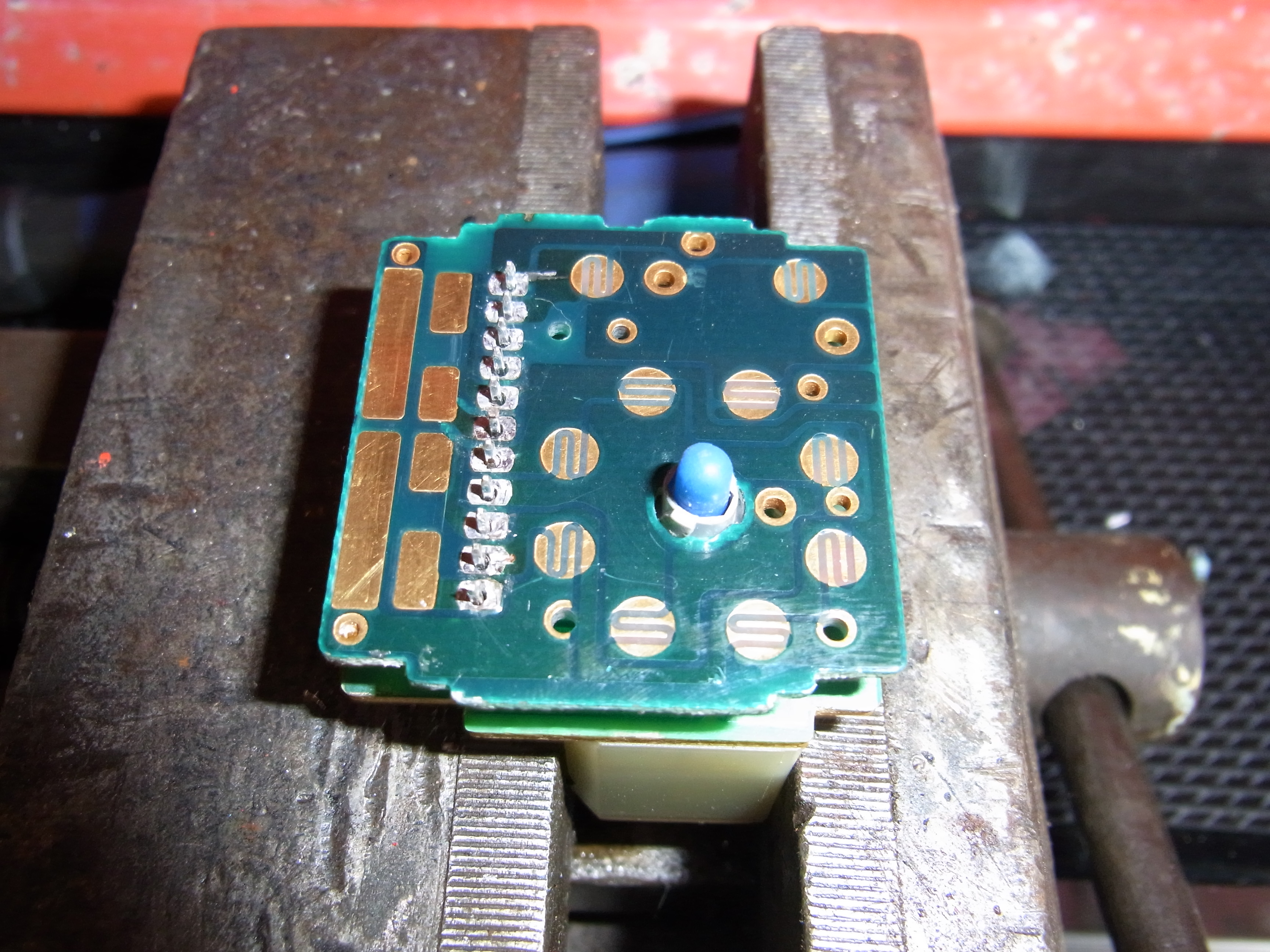
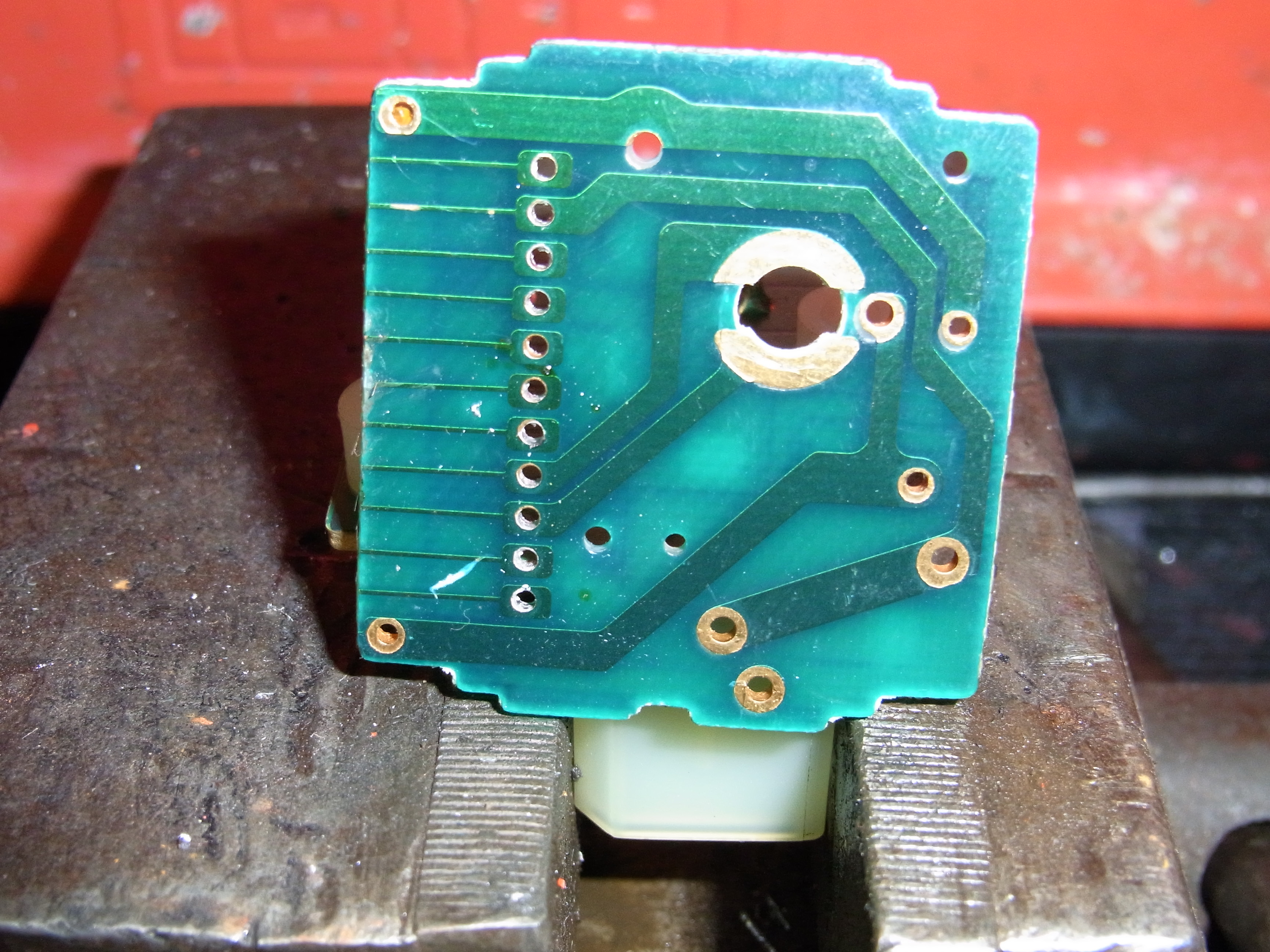
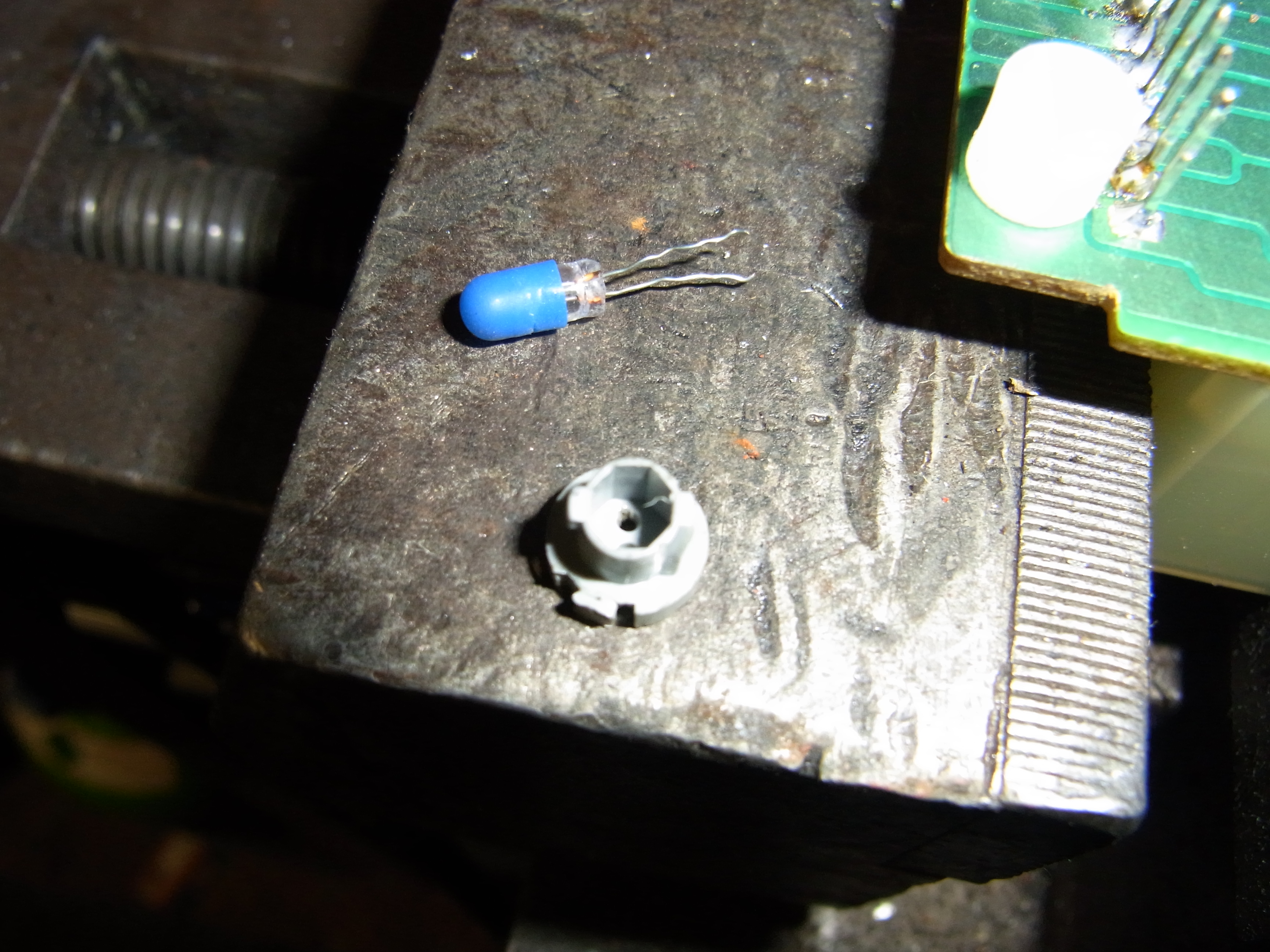
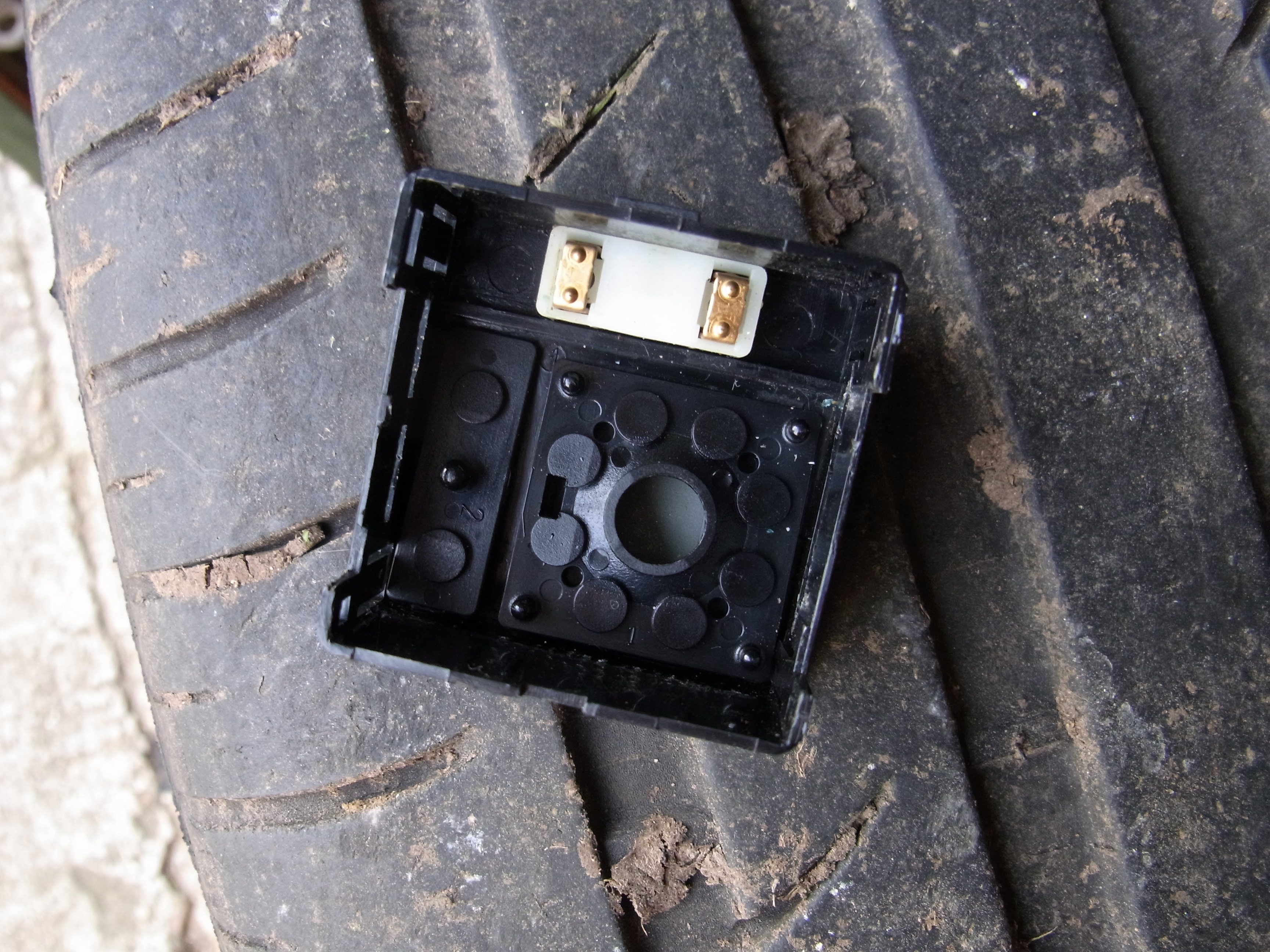
so I decided to investigate, not the smartest move, to disassemble you need to remove the two retaining plastics on the rear of the switch One marked “TOP” and on mine the other marked with a 70130 3995 stamp, these are held into the body of the switch with two small tangs on each that snap through cut outs in the body Once both of these are removed you then can gently prise out the circuit board by levering the switch body out just enough for the PCB to clear the case for this I used a stanley knife, Once you have unclipped the PCB it can be slid out of the switch case you are left with the PCB assembly The rubber comes off no problem, but has small mounting pins which locate it so be careful not to damage them. You would think that the bulb could then be removed, but that assumption is incorrect, you need to de-solder the 11 pins that hold the PCB to the base as the bulb is too tall to be removed through the gap. Once the solder joints have been cleaned (solder sucker required) you can carefully remove the PCB from the base, there are 3 white plastic posts that keep the PCB at a fixed distance from the base shown in photo please don’t loose them Once apart I did test the continuity of each of the pins to the connections where the wiring plug goes in case there were any poor joints, I did find some and remade the connections shown below (Pin in top right corner) I also cleaned the underside of the Rubber switch contacts Next job was to replace the Bulb, the bulb holder needs to be rotated to allow removal from the PCB Next photo shows rear of PCB with Bulb holder removed Once removed you can see that the 12v bulb is cap less and the contacts are wires through the bulb base I chose to replace the bulb its self and re-use the base as I could not find a replacement complete unit. The following photo is of the inside of the switch and I felt it good practice to clean the two copper contacts before re-assembly The Re-assembly is obviously the reverse but it is best to refit the PCB into the switch body with the switch body in the position shown in the above photo to prevent the inserts from being dislodged from their resting positions